Instruction manual tu_us, Sauter gmbh, 2t v h – KERN & SOHN TU 300-0.01US User Manual
Page 2
Sauter GmbH
Ziegelei 1
D-72336 Balingen
E-Mail: [email protected]
Tel: +49-[0]7433- 9933-199
Fax: +49-[0]7433-9933-149
Internet: www.kern-sohn.com
Instruction Manual
TU_US
TU_US-BA-e-1212
2
ceramics, epoxies, glass and other ultrasonic
wave well- conductive materials.
-
Four transducer models are available for special
applications included coarse grain material and
high temperature applications.
-
Zero adjustment function
- Sound velocity calibration function
-
Two- point calibration function
-
Two measurement modes: Single point mode
Scan mode
-
Coupling status indicator showing the coupling
status
-
Battery indication indicates the rest capacity of
the battery
- “Auto sleep” and “Auto power off” function to
conserve battery’s life
Optional software to transfer the memory data to
PC
- Optional thermal mini- printer to print the
measured data via RS-232 port.
1.3 Measuring principle
The digital ultrasonic thickness gauge determines the
thickness of a part or a structure by accurately measuring
The time required for a short ultrasonic pulse generated by
a transducer to travel through the thickness of the material,
to reflect from the back or inside surface and be returned
to the transducer. The measured two-way transit time is
devided by two to account for the down-and-back travel
path, and then multiplied by the velocity of sound in the
material. The result is expressed in following relationship:
2
t
v
H
×
=
Where: H ----
˃ thickness of the test piece
v ----
˃ sound velocity in the material
t ----
˃ the measured round-trip transit time
1.4 Configuration
No.
Item
Quan-
tity
Note
Stan-
dard
Con-
figu-
ration
1
Main body
1
2
Transducer
1
Model:
N05/90°
3
Couplant
1
4
Instrument Case
1
5
Operating
Manual
1
6
Screwdriver
1
7
Alkaline battery
2
AA size
8
Optio-
nal
Con-
figu-
ration
9
Transducer: N02
See
Table3-1
10
Transducer: N07
11
Transducer: HT5
12
Mini thermal
printer
1
13
Print cable
1
14
DataPro for
Thickness
Gauge
1
For use
on the
PC
15
Communication
Cable
1
1.5 Operation conditions
Temperature: -20°C up to +60°C
Storage temperature: -30°C up to 70°C
Relative humidity: ≤ 90%
In the surrounding environment any kind of vibrations
should be avoided, as well as magnetic fields, corrosive
medium and heavy dust.
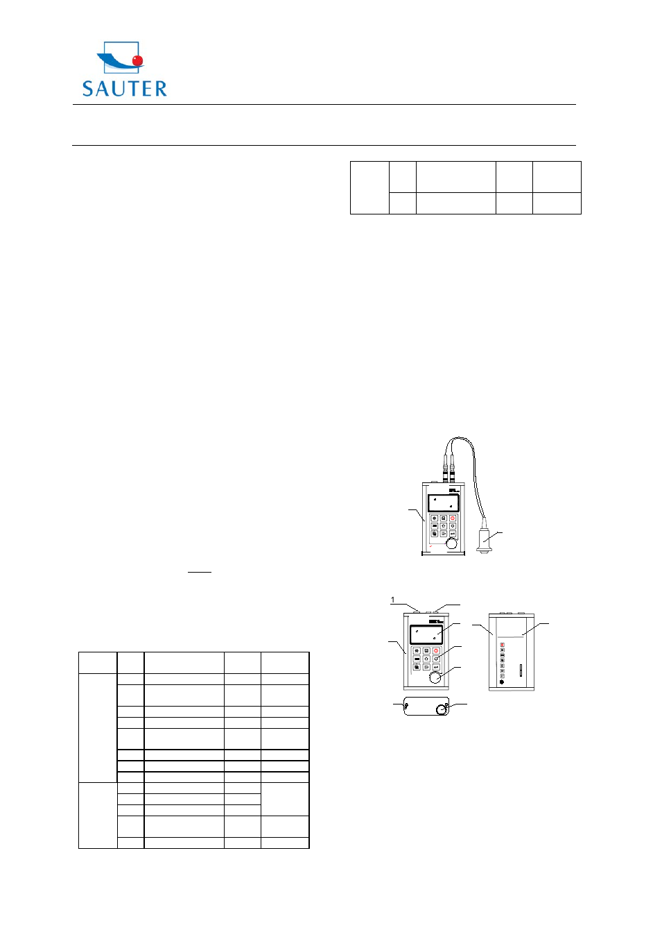
2. Structure feature
2.1 Instrument appearance
1 Main body
2 Transducer
2.2 Parts of the main body
1 Communication Socket
2 Aluminium case
3 Belt hole
4 Battery cover
5 Keypad
6 LCD Display
7 Socket of transducer (no polarity)
8 Control plate (inbuilt)
9 Aluminium case
10 Label
MT200
M iTec h
2
1
8. Enter
MiTech Inc. Ltd
5. Switch Selection
6. Save/Delete
7. Exit
3
M iTec h
4
8
2. Power On/Off
POWER: 2 X 1.5V
4. Probe Zero
OPERATION GUIDE
1. Plug in the transducer
3. Backlight On/Off
THICKNESS GAUGE
MT200
2
9
5
6
SN:
7
10