Explanation of ac symbols, Power cycle timing characteristics, Power cycle timing – Maxim Integrated DS80C390 User Manual
Page 55
DS80C390
55 of 58
110199
EXPLANATION OF AC SYMBOLS
This microcontroller uses timing parameters and symbols similar to the original 8051 family. The
following list of timing symbols is provided as an aid to understanding the timing diagrams.
t
Time
P
PSEN
A
Address
Q
Output data
C
Clock
R
RD
signal
CE
Chip Enable
V
Valid
D
Input data
W
WR
signal
H
Logic level high
X
No longer a valid logic level
L
Logic level low
Z
Tristate
I
Instruction
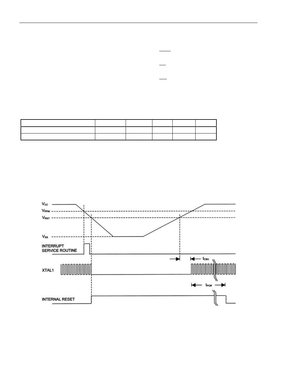
POWER CYCLE TIMING CHARACTERISTICS
PARAMETER
SYMBOL
TYP
MAX
UNITS
NOTE
Crystal start-up time
t
CSU
1.8
ms
1
Power-on reset delay
t
POR
65536
t
CLCL
2
NOTES FOR POWER CYCLE TIMING CHARACTERISTICS
1. Start-up time for crystals varies with load capacitance and manufacturer. Time shown is for an
11.0592 MHz crystal manufactured by Fox Electronics.
2. Reset delay is a synchronous counter of crystal oscillations during crystal start-up. Counting begins
when the level on the XTAL1 input meets the V
IH2
criteria. At 40 MHz, this time is approximately
1.64 ms.
POWER CYCLE TIMING
- DS5001FP (26 pages)
- MAX1416 (14 pages)
- MAX5865 (18 pages)
- DS33Z41 (167 pages)
- MAX1202 (7 pages)
- USBTO232 (31 pages)
- HFAN-09.5.0: Pattern Creator/Converter Software (8 pages)
- MAX-IDE MAXQ Microcontrollers (11 pages)
- MAX6876 Power-Supply Tracker/Sequencer (6 pages)
- MAX6877 Power-Supply Tracker/Sequencer (3 pages)
- 78Q8430 ARM9(920T) Linux Driver Diagnostic Guide (19 pages)
- 78Q8430 Software Driver (54 pages)
- 78Q8430 ST 5100/OS-20 with NexGen TCP/IP Stack (28 pages)
- 6612_OMU_S2_URT_V1_13 (56 pages)
- 6612_OMU_S2+2_URT_V1_14 (58 pages)
- 71M6511 Power Meter IC Family Software (137 pages)
- 71M65xx ADM51 ICE Safety Notice (2 pages)
- 71M6511 2-Layer Demo Board (2 pages)
- 71M6511 4-Layer Demo Board (2 pages)
- 78Q8430 Linux Driver ARM Platform (22 pages)
- 71M6513 Demo Board (2 pages)
- 71M6521DE Energy Meter IC Family Software (138 pages)
- 71M6521 Demo Board (2 pages)
- 71M6531 Demo Board (2 pages)
- 71M6531 Energy Meter IC Family Software (116 pages)
- 71M6533 Demo Board (2 pages)
- 71M6534H Demo Board (2 pages)
- 71M6515H Demo Board (2 pages)
- 73S1209F Evaluation Board (2 pages)
- 73S12xxF (38 pages)
- 73S12xxF Software (93 pages)
- 73S1210F Evaluation Board Lite (2 pages)
- 73S1210F Evaluation Board (2 pages)
- 73S1210F Multi-SAM Evaluation Board Lite (2 pages)
- 73S12xxF USB-CCID Linux DFU Host Application (8 pages)
- 73S1215F Device Firmware Upgrade Host Driver/Application (10 pages)
- 73S12xxF USB-CCID Host GUI (22 pages)
- 73S1215F Windows XP 32 USB CCID and DFU Drivers (15 pages)
- 73S1215F CCID USB Linux Driver (16 pages)
- 73S1215F Evaluation Board (2 pages)
- 73S1215F Evaluation Board Lite (2 pages)
- 73S1217F Evaluation Board (2 pages)
- 73S1217F Evaluation Board Lite (2 pages)
- MAXQ Family (216 pages)