External reset pins, Interrupts, Interrupt summary table 12 – Maxim Integrated DS80C390 User Manual
Page 24
DS80C390
24 of 58
110199
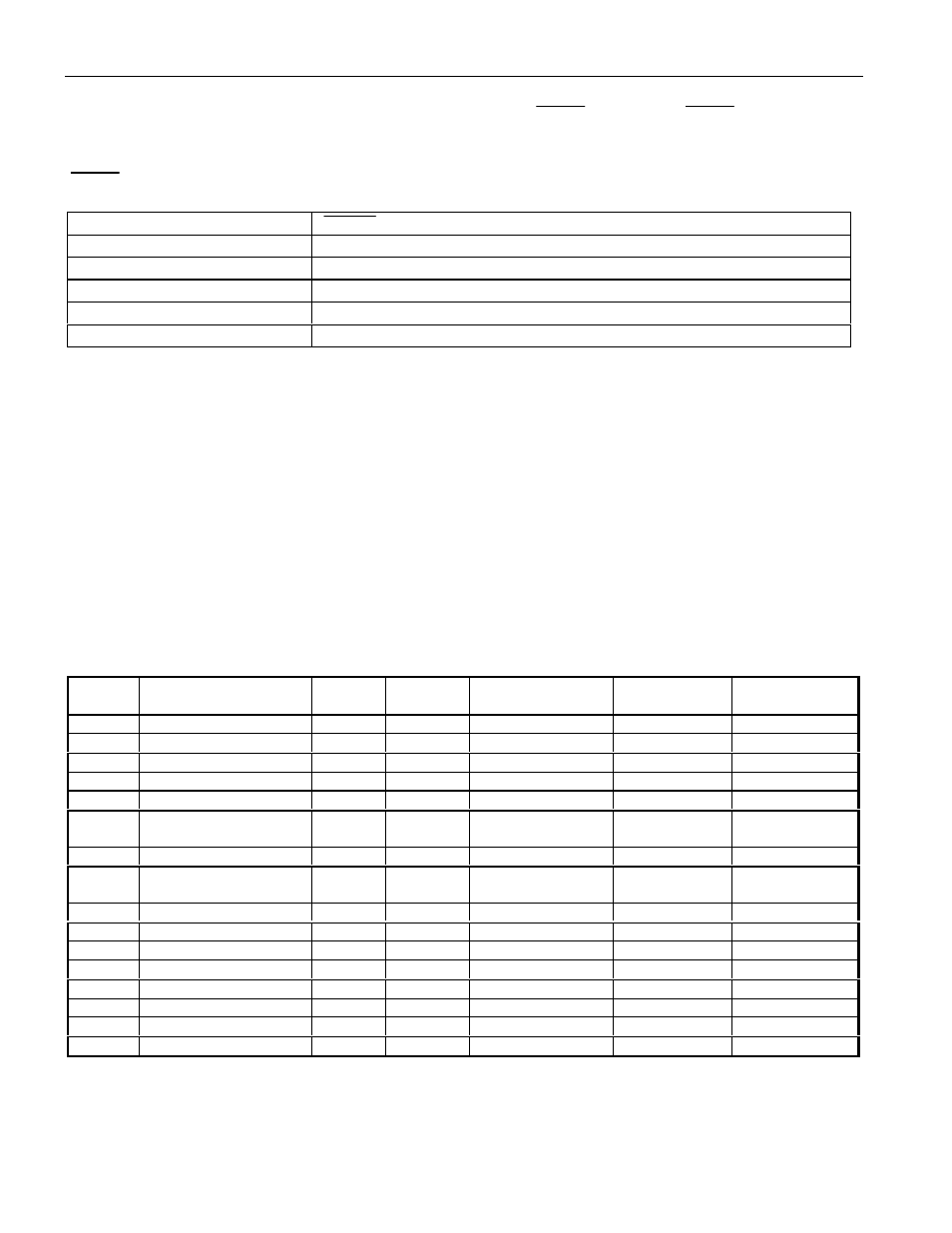
EXTERNAL RESET PINS
The DS80C390 has both reset input (RST) and reset output (
RSTOL
) pins. The
RSTOL
pin supplies an
active low Reset when the microprocessor is issued a Reset from either a high on the RST pin, a time out
of the watchdog timer, a crystal oscillator fail, or an internally detected power-fail. The timing of the
RSTOL
pin is dependent on the source of the reset.
Reset Type/Source
RSTOL
Duration
Power-on reset
65536 t
CLCL
(as described in Power Cycle Timing Characteristics)
External reset
< 1.25 machine cycles
Power fail
65536 t
CLCL
(as described in Power Cycle Timing Characteristics)
Watchdog timer reset
2 machine cycles
Oscillator fail detect
65536 t
CLCL
(as described in Power Cycle Timing Characteristics)
INTERRUPTS
The microcontroller provides 16 interrupt sources with three priority levels. All interrupts, with the
exception of the Power Fail interrupt, are controlled by a series combination of individual enable bits and
a global interrupt enable EA (IE.7). Setting EA to a 1 allows individual interrupts to be enabled.
Clearing EA disables all interrupts regardless of their individual enable settings.
The three available priority levels are low, high, and highest. The highest priority level is reserved for the
Power Fail Interrupt only. All other interrupt priority levels have individual priority bits that when set to
a 1 establish the particular interrupt as high priority. In addition to the user-selectable priorities, each
interrupt also has an inherent natural priority, used to determine the priority of simultaneously occurring
interrupts. The available interrupt sources, their flags, their enables, their natural priority, and their
available priority selection bits are identified in the following table.
INTERRUPT SUMMARY Table 12
NAME
DESCRIPTION
VECTOR NATURAL
PRIORITY
FLAG BIT
ENABLE BIT
PRIORITY
CONTROL BIT
PFI
Power Fail Interrupt
33h
0
PFI(WDCON.4)
EPFI(WDCON.5)
N/A
INT0
External Interrupt 0
03h
1
IE0(TCON.1)**
EX0(IE.0)
PX0(IP.0)
TF0
Timer 0
0Bh
2
TF0(TCON.5)*
ET0(IE.1)
PT0(IP.1)
INT1
External Interrupt 1
13h
3
IE1(TCON.3)**
EX1(IE.2)
PX1(IP.2)
TF1
Timer 1
1Bh
4
TF1(TCON.7)*
ET1(IE.3)
PT1(IP.3)
SCON0
TI0 or RI0 from serial
port 0
23h
5
RI_0(SCON0.0)
TI_0(SCON0.1)
ES0(IE.4)
PS0(IP.4)
TF2
Timer 2
2Bh
6
TF2(T2CON.7)
ET2(IE.5)
PT2(IP.7)
SCON1
TI1 or RI1 from serial
port 1
3Bh
7
RI_1(SCON1.0)
TI_1(SCON1.1)
ES1(IE.6)
PS1(IP.6)
INT2
External Interrupt 2
43h
8
IE2 (EXIF.4)
EX2 (EIE.0)
PX2 (EIP.0)
INT3
External Interrupt 3
4Bh
9
IE3 (EXIF.5)
EX3 (EIE.1)
PX3 (EIP.1)
INT4
External Interrupt 4
53h
10
IE4 (EXIF.6)
EX4 (EIE.2)
PX4 (EIP.2)
INT5
External Interrupt 5
5Bh
11
IE5 (EXIF.7)
EX5 (EIE.3)
PX5 (EIP.3)
C0I
CAN0 Interrupt
6Bh
12
various
C0IE (EIE.6)
C0IP (EIP.6)
C1I
CAN1 Interrupt
73h
13
various
C1IE (EIE.5)
C1IP (EIP.5)
WDTI
Watchdog Timer
63h
14
WDIF (WDCON.3)
EWDI (EIE.4)
PWDI (EIP.4)
CANBUS
CAN0/1 Bus Activity
7Bh
15
various
CANBIE (EIE.7)
CANBIP (EIP.7)
Unless marked, all flags must be cleared by the application software.
*
Cleared automatically by hardware when the service routine is entered.
** If edge triggered, flag is cleared automatically by hardware when the service routine is entered. If
level triggered, flag follows the state of the interrupt pin.