Watchdog time-out values table 11, Power fail reset, Power fail interrupt – Maxim Integrated DS80C390 User Manual
Page 23: And holds the processor in reset while v, Has risen above v, Drops below v
DS80C390
23 of 58
110199
during the debug process to determine where watchdog reset commands must be located in the
application software. The interrupt also can serve as a convenient time-base generator or can wake-up the
processor from power saving modes.
The Watchdog timer is controlled by the Clock Control (CKCON) and the Watchdog Control (WDCON)
SFRs. CKCON.7 and CKCON.6 are WD1 and WD0 respectively, and they select the Watchdog time-out
period. Of course, the
2X
4X/
(PMR.3) and CD1 :0 (PMR.7:6) system clock control bits also affect the
time-out period. Selection of time-out is shown below.
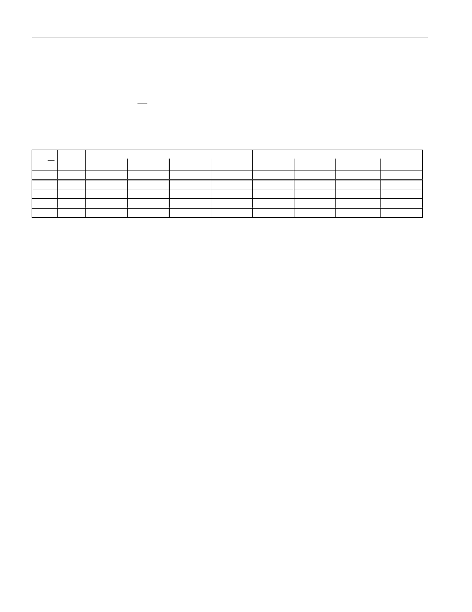
WATCHDOG TIME-OUT VALUES Table 11
WATCHDOG INTERRUPT TIME-OUT
WATCHDOG RESET TIME-OUT
2X
4X/
CD1:0
WD1:0=00
WD1:0=01 WD1:0=10 WD1:0=11 WD1:0=00 WD1:0=01
WD1:0=10
WD1:0=11
1
00
2
15
2
18
2
21
2
24
2
15
+512
2
18
+512
2
21
+512
2
24
+512
0
00
2
16
2
19
2
22
2
25
2
16
+512
2
19
+512
2
22
+512
2
25
+512
x
01
2
17
2
20
2
23
2
26
2
17
+512
2
20
+512
2
23
+512
2
26
+512
x
10
2
17
2
20
2
23
2
26
2
17
+512
2
20
+512
2
23
+512
2
26
+512
x
11
2
25
2
28
2
31
2
34
2
25
+512
2
28
+512
2
31
+512
2
34
+512
The table demonstrates that for a 33 MHz crystal frequency the Watchdog timer is capable of producing
time-out periods from 3.97 ms (2
17
* 1/33 MHz) to over two seconds (2.034 = 2
26
* 1/33 MHz) with the
default setting of CD1 :0 (=10). This wide variation in time-out periods allows very flexible system
implementation.
In a typical initialization, the user selects one of the possible counter values to determine the time-out.
Once the counter chain has completed a full count, hardware will set the interrupt flag
(WDIF=WDCON.3). Regardless of whether the software makes use of this flag, there are then 512 clocks
left until the reset flag (WTRF=WDCON.2) is set. Software can enable (1) or disable (0) the reset using
the Enable Watchdog Timer Reset (EWT=WDCON.1) bit.
POWER FAIL RESET
The microcontroller incorporates an internal precision band-gap voltage reference and comparator circuit
which provide a power-on and power-fail reset function. This circuit monitors the processor’s incoming
power supply voltage (V
CC
), and holds the processor in reset while V
CC
is below the minimum voltage
level. When power exceeds the reset threshold, a full power-on reset will be performed. In this way, this
internal voltage monitoring circuitry handles both power-up and power-down conditions without the need
for additional external components.
Once V
CC
has risen above V
RST
, the device will automatically restart the oscillator for the external crystal
and count 65,536 clock cycles before program execution begins at location 0000h. This helps the system
maintain reliable operation by only permitting processor operation when the supply voltage is in a known
good state. Software can determine that a power-on reset has occurred by checking the Power-On Reset
flag (POR;WDCON.6). Software should clear the POR bit after reading it.
POWER FAIL INTERRUPT
The band-gap voltage reference that sets a precise reset threshold also generates an optional early warning
Power-fail Interrupt (PFI). When enabled by software, the processor will vector to ROM address 0033h
if V
CC
drops below V
PFW
. PFI has the highest priority. The PFI enable is in the Watchdog Control SFR
(EPFI;WDCON.5). Setting this bit to logic 1 will enable the PFI. Application software can also read the
PFI flag at WDCON.4. A PFI condition sets this bit to a 1. The flag is independent of the interrupt
enable and must be cleared by software.