Hardware hookup, Crestron tps-ga-tpi isys, G-series touchpanel interface – Crestron electronic TPS-GA-TPI User Manual
Page 35
Crestron TPS-GA-TPI
Isys
®
G-Series Touchpanel Interface
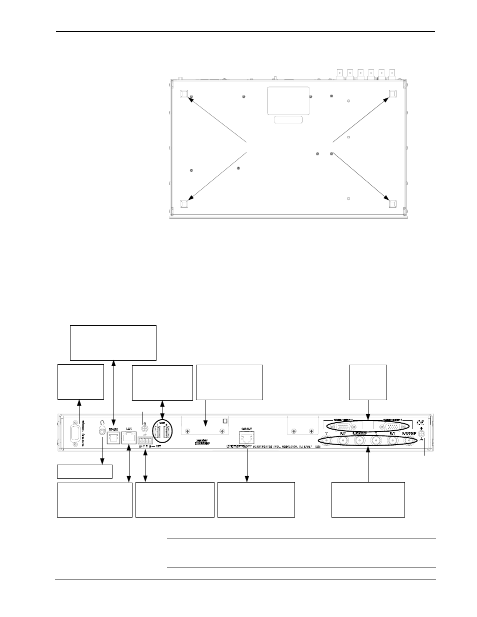
Foot Placement for the TPS-GA-TPI
PLACE FEET IN CORNERS
Hardware Hookup
Make the necessary connections as called out in the illustration that follows this
paragraph. Refer to “Network Wiring” on page 12 before attaching the 4-position
terminal block connector. Apply power after all connections have been made.
When making connections to the TPS-GA-TPI, use Crestron power supplies for
Crestron equipment.
Hardware Connections for the TPS-GA-TPI
LAN:
10 BaseT/100BaseTX
HIGH SPEED
ETHERNET TO LAN
GROUND
MEMORY
EXPANSION:
COMPACT FLASH
SLOTS
HEADPHONES
RGBHV
INPUT:
VIDEO IN
RGBHV
OUTPUT:
VIDEO OUT
RS-232:
TO COMPUTER,
MOUSE OR
TOUCHSCREEN INPUT*
USB:
MOUSE OR
TOUCHSCREEN
INPUT*
NET:
TO CONTROL
SYSTEM AND OTHER
CRESNET DEVICES
QM OUT:
QUICKMEDIA VIDEO
AND AUDIO OUTPUT
Y, P
B
/Y, P
R
/C/COMP:
VIDEO IN
GROUND
* Refer to “External Touchscreen” on page 32 for touchscreen input connections.
NOTE: The TPS-GA-TPI can only be powered by the 4-position terminal block
connector labeled NET. Crestron recommends an independent power supply for the
TPS-GA-TPI.
Operations Guide – DOC. 6609A
Isys
®
G-Series Touchpanel Interface: TPS-GA-TPI
• 31