Isys, G-series touchpanel interface crestron tps-ga-tpi – Crestron electronic TPS-GA-TPI User Manual
Page 12
Isys
®
G-Series Touchpanel Interface
Crestron TPS-GA-TPI
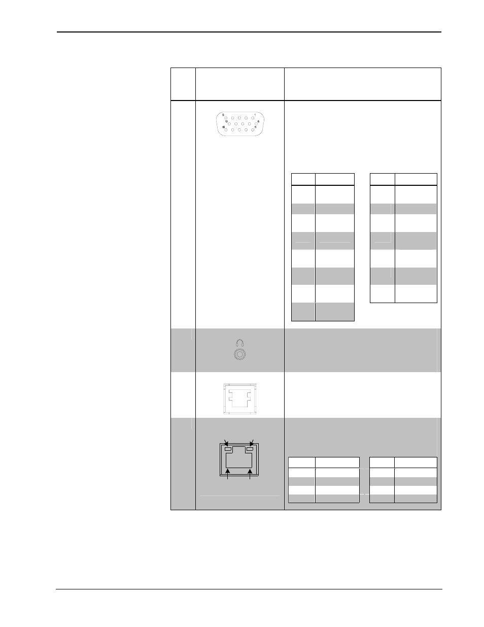
Connectors, Controls & Indicators (Continued)
#
CONNECTORS
1
,
CONTROLS &
INDICATORS
DESCRIPTION
3
RGBHV OUTPUT
(1) DB15 HD female, RGB output;
Format: RGBHV;
Output resolution
2
: Software selectable
800 x 600, 1024 x 768, 1280 x 768,
1366 x 768, 1152 x 864, 1280 x 1024
Sync output type: RGBHV
Sync output level: TTL, 4.0 V
p-p
Vertical frequency: 60 Hz fixed
PIN SIGNAL
PIN SIGNAL
1 Red
9 No
Connect
2
Green
10
Ground
3 Blue
11 No
Connect
4
Reserved
12
No
Connect
5 Ground
13
Horizontal
Synch
6
Red
Ground
14
Vertical
Synch
7 Green
Ground
15 No
Connect
8
Blue
Ground
4
HEADPHONES
(1) 3.5 mm TRS mini phone jack;
Stereo headphone or unbalanced stereo line
level audio output;
Output power: 12 mW per channel;
Minimum impedance: 32 Ω
5
RS-232
(1) 6-pin RJ-11 female;
Computer console or mouse/touchscreen
input port
2, 3
;
Bidirectional RS-232 up to 115.2 k baud;
Hardware and software handshaking support
6
LAN
GREEN
LED
YELLOW
LED
PIN 8
PIN 1
(1) 8-wire RJ-45 with two LED indicators;
10BaseT/100BaseTX Ethernet port;
Green LED indicates link status;
Yellow LED indicates Ethernet activity
PIN
SIGNAL
PIN
SIGNAL
1
TX +
5
N/C
2
TX -
6
RC -
3
RC+
7
N/C
4
N/C
8
N/C
(Continued on following page)
8
• Isys
®
G-Series Touchpanel Interface: TPS-GA-TPI
Operations Guide – DOC. 6609A