Crestron tps-ga-tpi isys, G-series touchpanel interface – Crestron electronic TPS-GA-TPI User Manual
Page 13
Crestron TPS-GA-TPI
Isys
®
G-Series Touchpanel Interface
Connectors, Controls & Indicators (Continued)
#
CONNECTORS
1
,
CONTROLS &
INDICATORS
DESCRIPTION
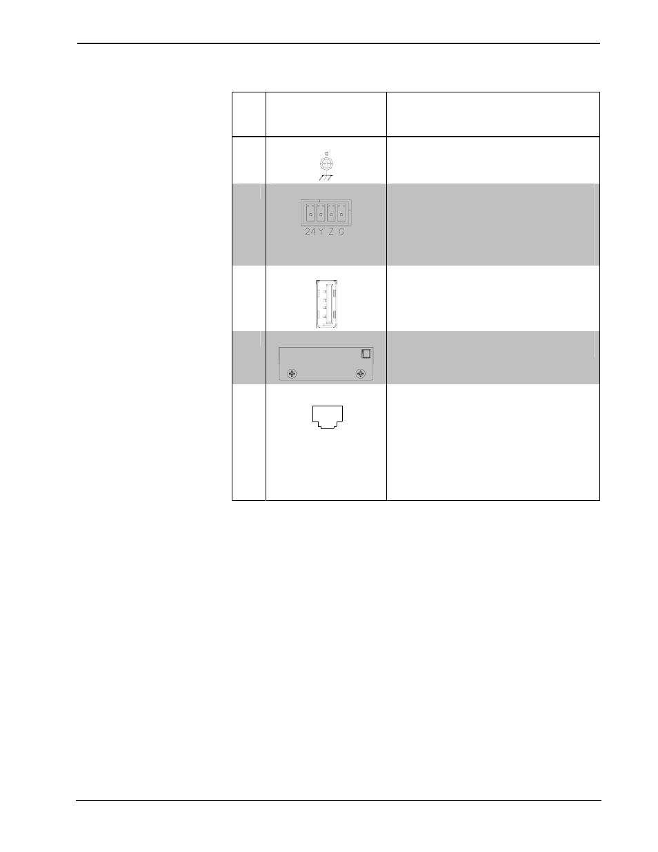
7
G
(2) 6-32 screw, chassis ground lug
8
NET
Four-position terminal block connector for
data and power. Connects to Cresnet control
network.
Pin 1 (24) Power (24 Volts DC)
Pin 2 (Y)
Data
Pin 3 (Z)
Data
Pin 4 (G)
Ground
9
USB
1
2
3
4
(2) USB 1.1 Type A female
for mouse or touchscreen input
2
10
MEMORY
(1) Type II Compact Flash card slot for
memory expansion
11
QM OUT
4
1
8
(1) 8-wire RJ-45 female, QuickMedia output
port containing RGB (same as RGBHV
OUTPUT
) and WAV file audio;
Format: RGBHV;
Output resolution
2
: Software selectable
800 x 600, 1024 x 768, 1280 x 768,
1366 x 768, 1152 x 864, 1280 x 1024
Connects to QM input port of any
QuickMedia device via CresCAT-QM or
CresCAT-IM cable
(Continued on following page)
Operations Guide – DOC. 6609A
Isys
®
G-Series Touchpanel Interface: TPS-GA-TPI
• 9