2 using the turbo waste gate control – Haltech F10 User Manual
Page 78
73
16.2.2 Using the Turbo Waste Gate Control
In order to use the Turbo Waste Gate Control function, you will need the following:
A suitable pressure solenoid valve (available from your Haltech Dealer);
Air hose and fittings;
F10A programming software and cable;
An overboost relief valve (strongly recommended).
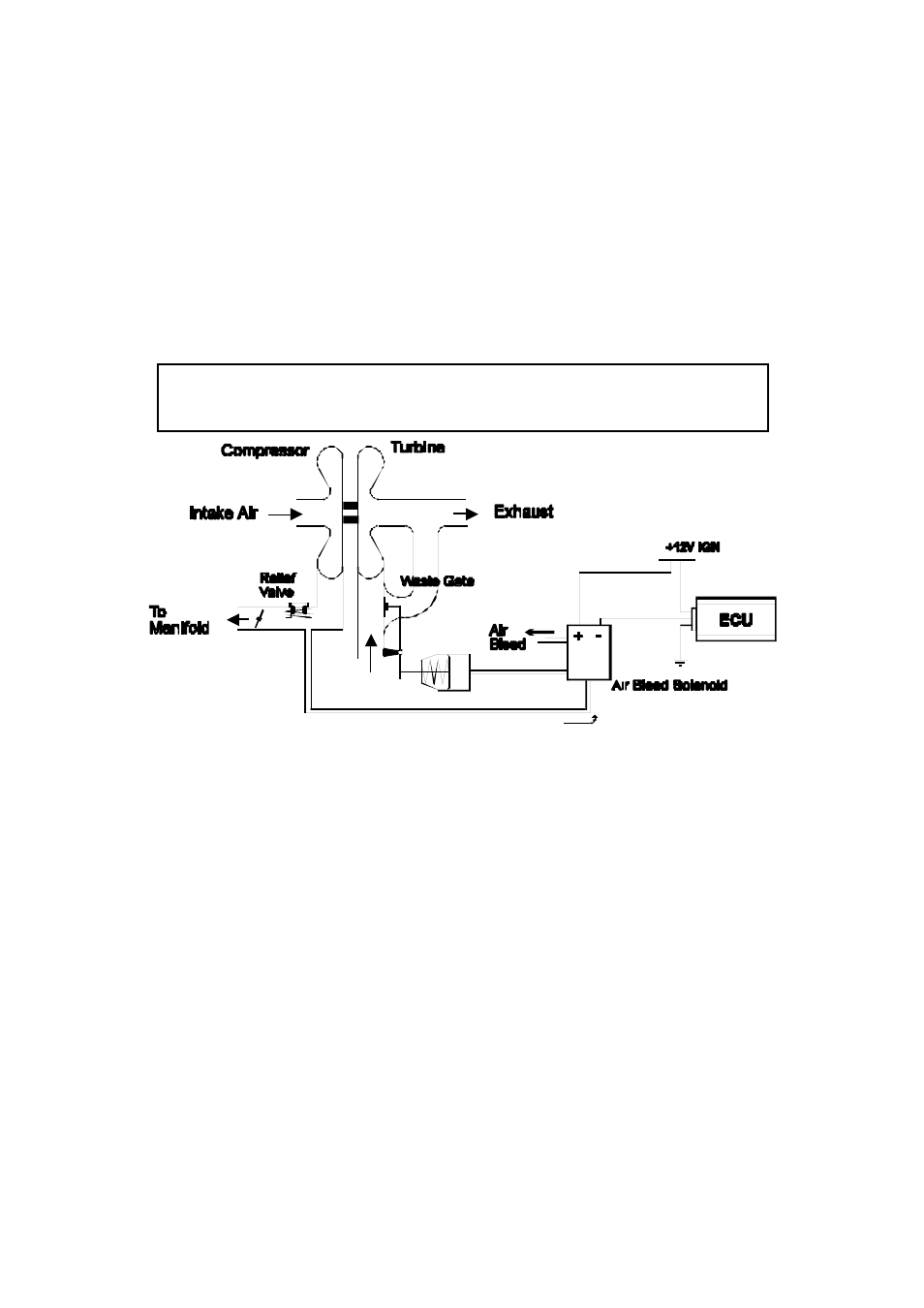
The air circuit to the waste gate must be configured appropriately, as in figure 16.2. Install the
solenoid valve securely, and power and signal from the output connector on the harness. The
wastegate should be re-set so that its operation point is very low, around 20kPa (3 psi).
Note: Be sure to use air hose that is rated to the pressure the engine is expected
to be boosted to. All fittings should be secured so that they will not disconnect
under high pressures.
Figure 16.2. Diagram of Turbo with Wastegate Control Solenoid.
A relief valve should be fitted to the manifold as a backup in case of an air hose failure and
uncontrolled boost.
Once the solenoid installation is complete run the F10A software in ONLINE mode. Select
the Turbo Wastegate Control Function on the appropriate output channel, and set the
following parameters.
Period
This sets the period of oscillation of the solenoid. M ost solenoids will operate at
around 30Hz, which corresponds to a period of about 30ms. Enter the desired
oscillation period in milliseconds here.
Use Map
This sets which map (map 1 or map 2) is used to perform waste gate control. The
reason for having two maps is so one map can be tuned for street driving and the other
for racing. The two turbo waste-gate maps are found in the M aps menu of the F10
software