2 installation summary, 3 expanded installation guide, Manifold absolute pressure (map) sensor – Haltech F10 User Manual
Page 16
11
1.2 Installation Summary
- M ount M anifold Absolute Pressure Sensors
- M ount Coolant Temperature Sensors
- M ount Inlet Air Temperature Sensors
- M ount Throttle Position Sensors
- M ount optional Exhaust Gas Oxygen Sensor (if used)
- Route M ain Wiring Harness and connect sensors
- M ount and connect Power Relays
- M ount Fuse Block
- M ount ECU inside passenger compartment
- Locate and connect flying wires:
RED
+ 12 volts battery
GREY
Ignition on 12 volts
BLACK Chassis
ground
ORANGE
(2 wires) Fuel Pump Circuit
- Connect Trigger signal
- Connect ECU and test.
F10A and F10A-8 Only
- Install and connect the optional Idle Speed M otor
- Install and connect any Optional Outputs
1.3 Expanded Installation Guide
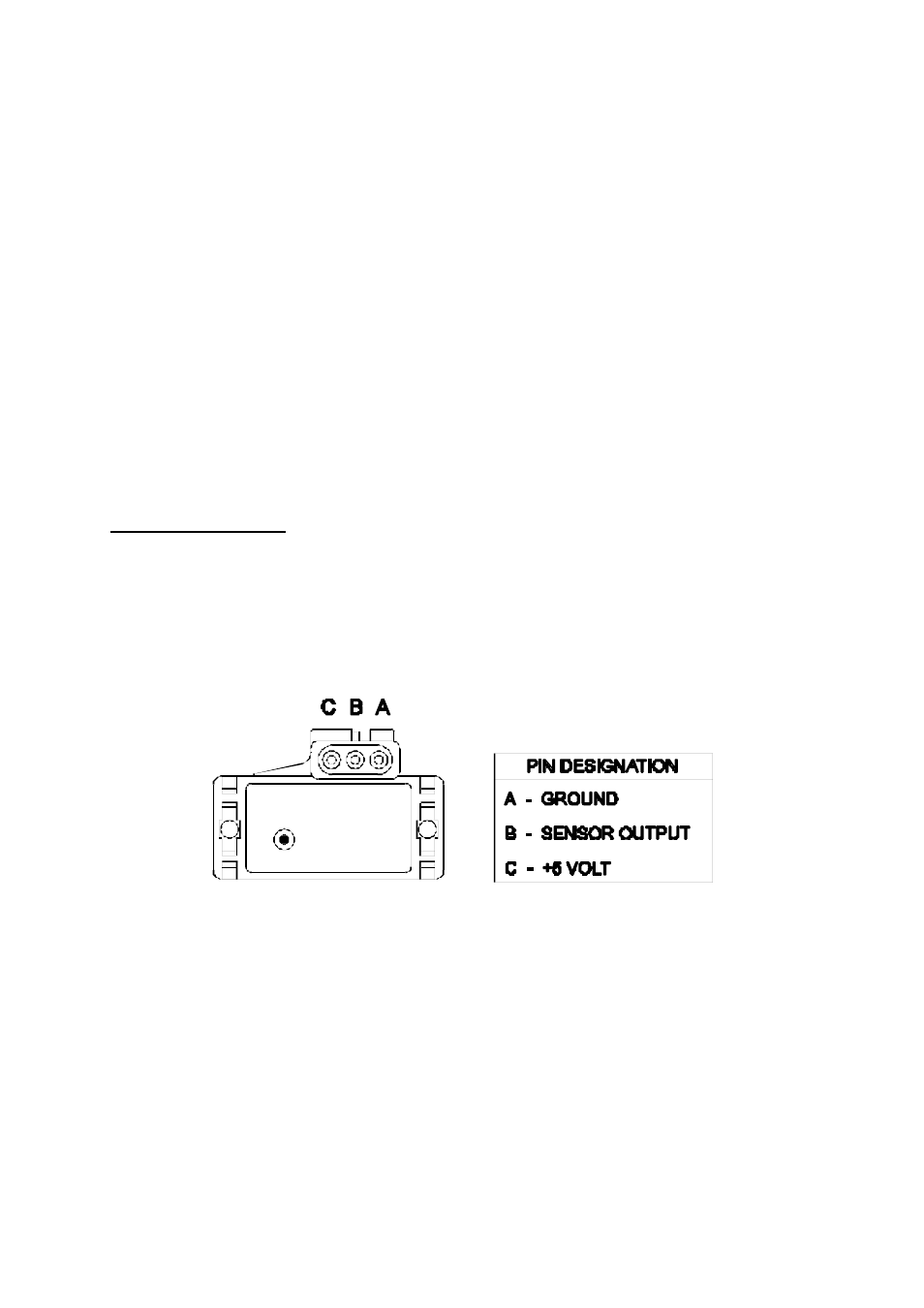
1.3.1. Manifold Absolute Pressure (MAP) Sensor
The MAP sensor is used to convert the manifold pressure into an electrical signal for the F10
ECU to use. The sensor works in absolute pressures, thus its calibration is not affected by
changes in barometric pressure. The vacuum and, in the case of forced air induction engines,
the pressure under boost, is proportional to the load under which the engine is operating and
the ECU uses the electrical signal as a load reference.
There are three types of M AP sensors that can be used with F10 system. Which sensor is
required depends on the engine set-up.
1 Bar Sensor (Part No. 039 4070)
(-100kPa to 0 kPa)
Normally Aspirated Engines