Great Planes Tracer 46 Kit - GPMA0400 User Manual
Page 5
5
There are two types of screws used in this kit:
Sheet metal screws are designated by a number and a
length. For example #4 x 5/8"
Machine screws are designated by a number, threads per
inch and a length. For example 2-56 x 5/8"
When you see the term “test fit” in the instructions, it
means you should first position the part on the assembly
without using any glue, then slightly modify or “custom fit”
the part as necessary for the best fit. Do not glue until told
to do so.
When you see the term “fit” in the instructions, it means
you should first position the part on the assembly without
using any glue, then modify or “custom fit” the part as
necessary for the best fit. Glue when you are satisfied with
the fit.
Where you see the term “glue”, it is at your option to select
the thickness of CA with which you are most comfortable. If
the step indicates a particular thickness of glue, be sure to
use the thickness recommended for strength, penetration
and/or working time.
Whenever just “epoxy” is specified you may use either 30-
minute epoxy or 6-minute epoxy. When 30-minute epoxy is
specified it is highly recommended that you use only 30-
minute epoxy because you will need the working time
and/or the additional strength.
Several times during construction we refer to the “top” or
“bottom” of the model or a part of the model. For example,
during wing construction we may tell you to “glue the top
main spar” or “tr im the bottom of the for mer.” It is
understood that the “top” or “bottom” of the model is as it
would be when the airplane is right-side-up and will be
referred to as the “top” even if the model is being worked on
upside-down. I.E. the “top” main spar is always the “top”
main spar even when the wing is oriented upside-down.
Fuse = Fuselage
Stab = Horizontal stabilizer
Fin = Vertical fin
LE = Leading edge (front)
TE = Trailing edge (rear)
LG = Landing gear
Ply = Plywood
Bass = Basswood
" = Inches
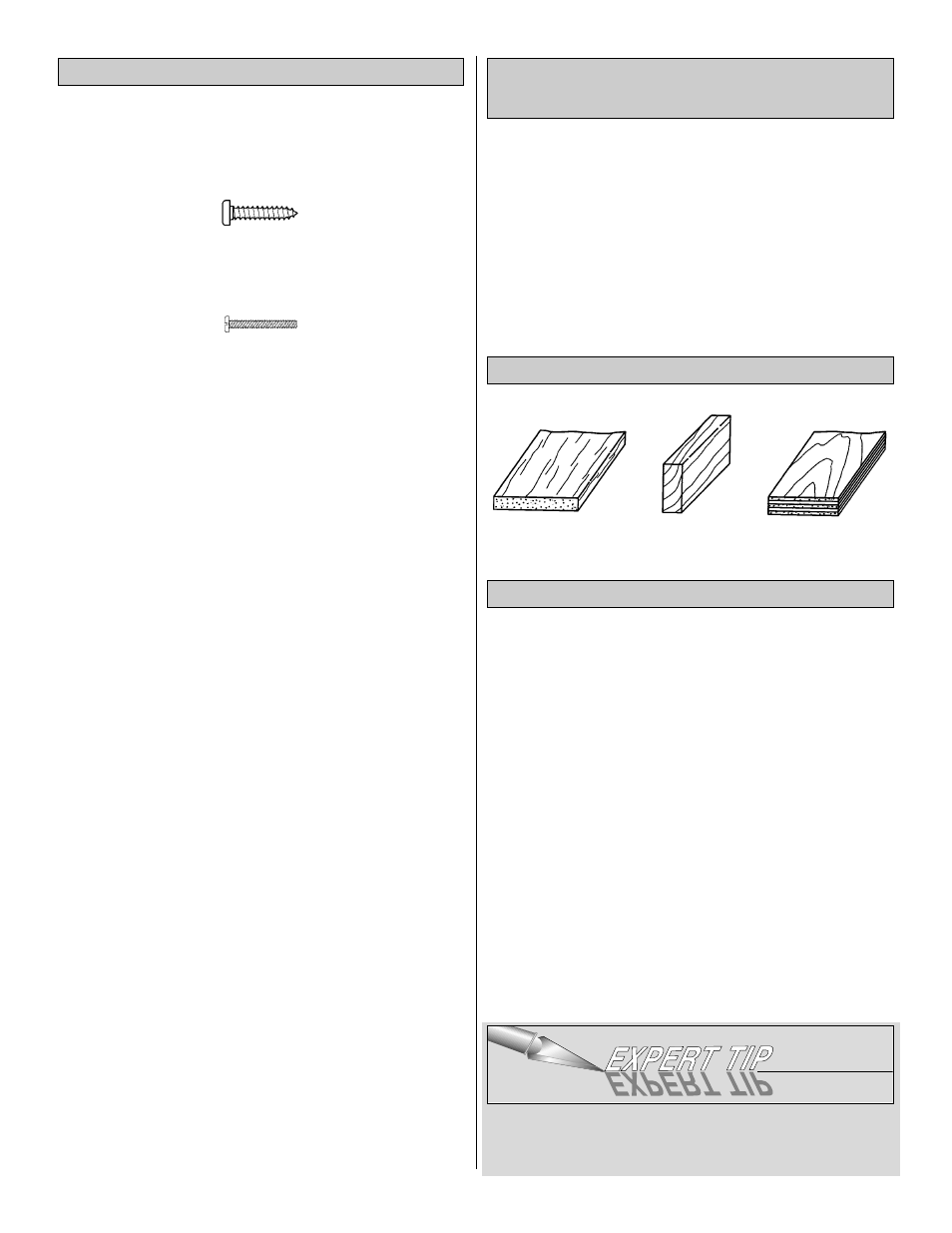
Balsa Basswood Plywood
❏
1. Unroll the plan sheets. Re-roll the plans inside out to
make them lie flat.
❏
2. Remove all parts from the box. As you do, figure out
the name of each part by comparing it with the plans and
the parts list included with this kit. Using a felt tip or ball
point pen, lightly write the part name or size on each piece
to avoid confusion later. Use the die-cut patterns shown on
pages 6 and 7 to identify the die-cut parts and mark them
before removing them from the sheet. Save all leftovers. If
any of the die-cut parts are difficult to punch out, do not
force them! Instead, cut around the parts with a hobby
knife. After punching out the die-cut parts, use your Bar
Sander or sanding block to lightly sand the edges to
remove any die-cutting irregularities or slivers.
❏
3. As you identify and mark the parts, separate them into
groups, such as fuse (fuselage), wing, fin, stab (stabilizer)
and hardware.
Zipper-top food storage bags are handy to store the small
parts as you sort, identify and separate them into sub-
assemblies.
Get Ready to Build
Types of Wood
Common Abbreviations Used in this
Manual and on the Plans
Building Notes