Attach the canopy install the hardware – Great Planes Tracer 46 Kit - GPMA0400 User Manual
Page 38
❏
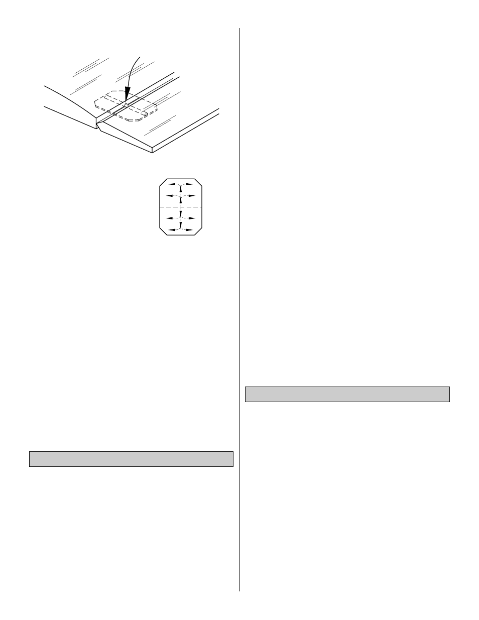
4. Remove the pin and add 6 drops of thin CA to the
center of all the hinges on both the top and the bottom.
Do not use accelerator on any of the hinges. Do not glue
the hinges with anything but thin CA and do not attempt
to glue one half of the hinge at a time with medium or
thick CA. They will not be properly secured and the
controls could separate while the model is in flight.
❏
5. Join the rudder to the fin with the hinges and use 30-
minute epoxy to simultaneously glue the tail gear wire in
the rudder and the tail gear bearing in the fuse. Do not
glue the nylon bearing to the rudder. Glue the hinges in
position with thin CA.
❏
6. Prepare the hinge slots in the ailerons the same way
you did for the tail surfaces. Glue the hinges with thin CA.
❏
1. Assemble the fuel tank per the manufacturer's
instructions. Install in the fuse with approximately 12" of fuel
line each for the pickup and the vent lines on the tank.
❏
2. Install a 1" tail wheel with a 3/32" wheel collar.
❏
3. Reinstall your retracts or fixed gear in the manner you
trial fitted them earlier.
❏
5. Install the elevator, rudder and throttle pushrods, then
install the control horns and hook them up the same way
you did earlier.
❏
6. Wrap the receiver and battery pack in at least 1/4" of
foam rubber, then test fit them in the location shown on the
plan. Do not permanently mount your receiver or battery
pack until you have verified the C.G. (page 39).
❏
7. Mount the receiver switch in a convenient location that
will not interfere with the servos and pushrods inside
the fuselage.
❏
8. Route the receiver antenna. On our prototype we
used the fourth pushrod tube to route the antenna to the
rear of the fuse, then taped it to the fuse.
❏
9. Some modelers prefer to cushion the wing with wing
seating foam tape on the wing saddle of the fuselage. Apply
1/16" seating tape on the wing saddle of the fuselage if
you choose.
❏
10. Prepare the engine compartment for installing the cowl
by connecting the fuel lines, installing a fueling valve (not
provided), mounting the muffler and connecting the throttle
pushrod. Install the cowl, then mount the spinner back plate,
prop, prop washer and prop nut. Install the spinner.
❏
1. Place the canopy on the fuselage in the location
shown on the plan, then temporarily hold it in position with
tape. Hint: We chose to paint the canopy and thus avoid
the added weight of a pilot. If you wish to select and install
a pilot, do so now. You may want to mount it on a small
balsa base, which can be glued to the MonoKote cockpit
covering without additional weight.
❏
2. Use a felt tip pen to accurately trace the canopy
outline onto the MonoKote film covering.
❏
3. Using the lines you just drew as a reference, glue the
canopy to the fuselage using rubber bands or masking tape
to hold it in position until the glue dries. We recommend a
glue specifically formulated for gluing on canopies such as
Pacer “Formula 560” canopy glue. Formula 560 is like
regular white glue (aliphatic resin) in that it dries clear and
cleans up with water but sticks extremely well to butyrate
and dries overnight (to allow for accurate positioning).
Attach the Canopy
Install the Hardware
THE CA WICKS
ALONG THE "TUNNELS"
TO THE ENTIRE
HINGE SURFACE
ASSEMBLE, THEN APPLY 6 DROPS
OF THIN CA TO CENTER
OF HINGE, ON BOTH SIDES
38