Great Planes Tracer 46 Kit - GPMA0400 User Manual
Page 34
in the sketch and on the plan. Use a ballpoint pen to mark
the location of the control horn mounting holes and drill
3/32" holes at the marks. Temporarily mount the control
horns to the elevators with the backing plates and 2-56
x 5/8" screws.
❏
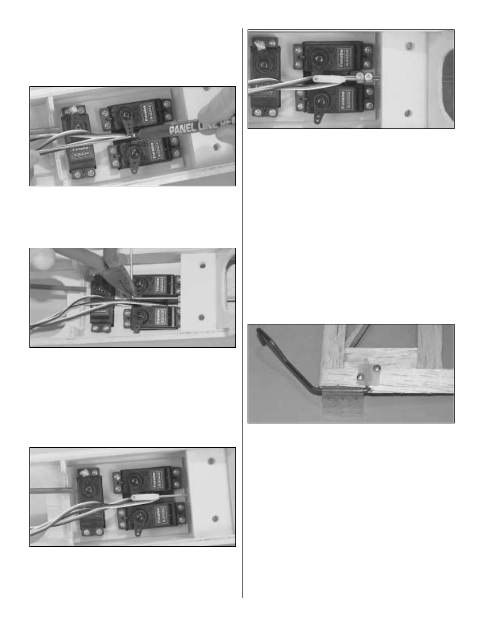
9. With the elevator servo in place, the servo arm
perpendicular to the pushrod and the control surfaces in
neutral position, use a felt tip pen to mark where one
pushrod crosses the mounting holes in the servo arm.
❏
10. Disconnect the clevis from the control horn on the
wire you marked. Make a 90-degree bend at the mark you
made. Temporarily install a nylon Faslink on this pushrod,
then cut the wire so it slightly protrudes out of the Faslink.
Hint: If you prefer to bend and cut the pushrod outside the
fuselage, remove the pushrod, then make the 90-degree
bends and cut the wire. Unscrew the clevis and reinstall the
pushrod in the guide tube from the front, then screw the
clevis back on.
❏
11. Connect the bent pushrod to the servo with the
Faslink. If necessary, enlarge the hole in the servo arm with
a 5/64" drill bit (or a #48 bit for precision). Cut the second
pushrod 1/8" behind the Faslink (being sure the elevator
half is neutral).
❏
12. While keeping both elevators centered, connect the
two elevator pushrods to each other with two 5/32" wheel
collars and 6-32 x 1/4" hex head cap screws as shown in
the photo. We recommend using thread locking compound
on the cap screw threads.
❏
13. Temporarily mount the rudder with the hinges the
same as you did with the elevators. DO NOT GLUE.
❏
14. Mark the location of the tail gear wire on the rudder
and the nylon tail gear bearing on the fuselage. Remove the
rudder and drill a 7/64" hole in the leading edge of the
rudder at the mark you made for the tail gear wire. Cut a
groove in the LE of the rudder for the nylon tail gear bearing.
Test fit the tail gear wire in the rudder.
❏
15. Mount the control horn to the rudder, trapping the tail
gear wire between the screws.
❏
16. Cut a slot in the aft edge of the fuse (the fin post) at
the marks you made for the nylon tail gear bearing.
Without using any glue, join the rudder to the fin with the
tail gear bearing and hinges.
❏
17. Hook up the rudder pushrod the same as you did
with the first elevator.
❏
18. Mount the aileron servos in the wing with the screws
provided with the radio.
34