Retract servo and linkage installation – Great Planes Tracer 46 Kit - GPMA0400 User Manual
Page 18
❏
5. Position the wing on the jigs. When satisfied that the
wing is joining properly, lift it off the work surface and
liberally coat the wing joiner and spars with epoxy and
position in place. Place the wing back on the jigs and glue
the retract servo tray in and the TEs of the wing panels
together with thin CA. Weight the wing and leave it
undisturbed until the epoxy has fully cured.
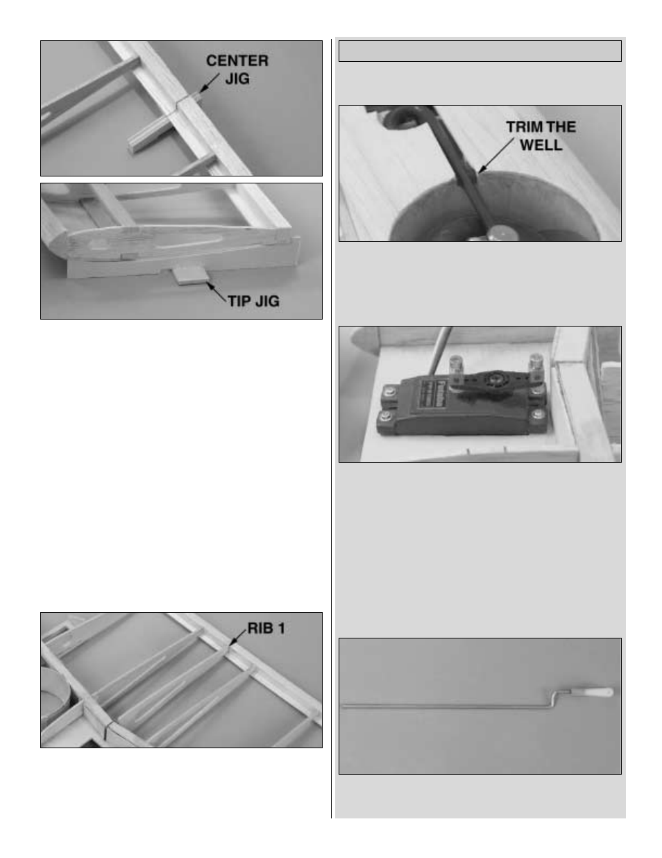
❏
6. Glue the die-cut 3/32" balsa rib 1 in place.
If you are using fixed gear, skip to the Finish the Top of
the Wing section.
RETRACT INSTALLATION
❏
1. Trim the wheel wells where the struts make contact
so the retracts can lock in the “up” position.
❏
2. Find a servo horn with the outer holes at 1-1/16" to
1-1/8" from each other. Mount a Screw-Lock Pushrod
Connector (GPMQ3870, not included) in both outer
holes. Hint: The standard S6-arm Futaba servo horn
works well — just trim off the 4 arms that are not needed.
❏
3. Mount your retract servo, using the hardware
supplied with the servo.
❏
4. Cut 5/8" of the threads off the end of two 12"
pushrods with clevises attached (GPMQ3772, not
included). Bend to the shape as shown on the plans.
Retract Servo and Linkage Installation
18