Great Planes Tracer 46 Kit - GPMA0400 User Manual
Page 23
❏
3. Using a straightedge and a pen, draw a line horizontally
across the firewall from the left outer punch mark to the right
outer punch mark. Draw a line vertically from the top punch
mark to the bottom punch mark. The intersection of these
two lines is the center of the engine mount. Note: The center
of the engine mount is offset to compensate for the built-in
right and down thrust so that the crankshaft will exit the cowl
dead center on the fuselage centerline.
❏
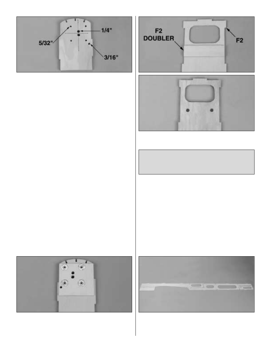
4. If you are using the included Great Planes adjustable
.40-.70 motor mount, drill the four 5/32" holes at the punch
marks as shown in the photo. Drill the two 1/4" holes and
the 3/16" hole as shown in the photo. NOTE: This throttle
exit placement works for the recommended 2-stroke
engines, clearing the exhaust, as well as 4-stroke engines
with the carburetor rotated 180-degrees.
❏
5. Press the four supplied 6-32 blind nuts into the holes
on the back of the firewall. Gently tap the blind nuts with a
hammer to fully seat them into the firewall, then add a few
drops of thin CA around the blind nuts to secure them.
❏
6. Glue the die-cut 1/8" ply F2 doubler to the front side
of die-cut 1/8" ply F2 as shown on the plans.
❏
7. Drill two 1/4" holes through the punch marks in former
F-2 and through the F2 doubler. Hint: Place the former on a
leftover piece of wood and press down as you drill the hole
so the former does not split when drilled.
❏
8. Cover the fuse side view of the plans with Great
Planes Plan Protector. Fit and glue the die-cut 1/8" balsa
forward, center and fuse sides together over the plan as
shown in the photo.
IMPORTANT NOTE: The front side of this one former is the
side which is NOT embossed and which does NOT have
punch marks. This fuse former is the only former which is
installed with the embossing facing the tail of the model.
23