Build the fin/rudder – Great Planes Spitfire 40 Kit - GPMA0179 User Manual
Page 7
❏ ❏
8. Select two 1/16" x 1/4" x 24" strips for the stab outer
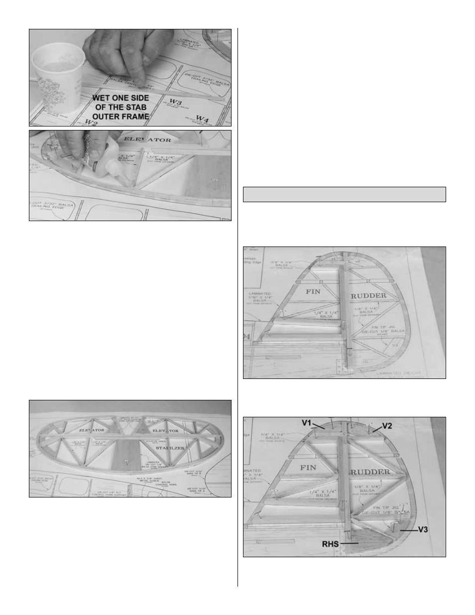
frame. Wet one side of the first strip by dipping your finger in
water, then running it along the one side of the strip. Take care
not to wet both sides. Using medium CA, secure the dry side of
the strip to the middle of the stab center working toward the tip.
Note: Water accelerates CA much like commercial accelerators,
so be careful not to get anything wet that should not be.
Hint: Another way to wet the strips is by holding them in the air
and spraying with a spray bottle. Do not spray the strips while
sitting on a flat surface, or both sides will get wet.
❏ ❏
9. Slowly wrap the strip from the stab center all the way
around to the inboard elevator roots, securing it with thin CA as
you go. Take care to stay tight against the ribs, leading and
trailing edges, and jigs. Remember not to glue to the jigs.
❏
10. Repeat steps 8 and 9 for the left side of the stab.
❏
11. Wet one side of the next strip. Turn it over and lay a bead
of medium CA down the other side. Staggering the joint 1/2"
from all previous joints, but being sure to keep the joints
supported by the stab center, glue the next strip onto the
previous one. Trim the strip flush with the elevator inboard root.
Note: If you can work fairly quickly, the last applied strip will still
be wet on the outside. This will accelerate the CA, securing the
strips to one another immediately. If you crack the strip, don’t
worry. Just hold it in place until the medium CA cures and then,
seal it with thin CA if necessary.
❏
12. Apply the remaining 5 strips. Remember to stagger the joints.
❏
13. Unpin the stab from the plans and remove the jigs.
Inspect all glue joints and re-glue with CA as necessary. Use a
bar sander or a large sanding block and 220-grit sandpaper to
sand the entire top and bottom surface of the stab framework
until it is flat and even. Be careful while sanding so that you do
not over-thin any one particular area of the stab or gouge the
stab ribs by snagging the sandpaper on them.
❏
14. Round all edges of the stab and elevators to the shape
shown on the cross-section on the plans. Hint: Labeling the
elevators “left” and “right,” and labeling the bottom of the stab,
will ensure proper assembly later.
❏
15. Cut the stab outer frame between the elevator angled
leading edges and stab angled trailing edges, separating the
elevators from the stab. Sand the outer frame smooth.
Don’t forget to cover the fin area of the plan with Great Planes
Plan Protector so the glue won’t stick to the plan. DO NOT cut
the vertical fin plan from the fuselage plan.
❏
1. Using the leftover 1/4" x 1/4" balsa stick from the stab, cut,
fit, pin and glue all 1/4" sticks into the fin and rudder, being
careful not to glue any fin pieces to any rudder pieces.
❏
2. Note: Refer to this photo for the following four steps.
Laminate the two die-cut 1/8" balsa rudder horn supports RHS
making the rudder horn support.
Build the Fin/Rudder
7