Mount the tailgear – Great Planes Spitfire 40 Kit - GPMA0179 User Manual
Page 28
leftover from the molding process so that the halves fit
together well.
❏
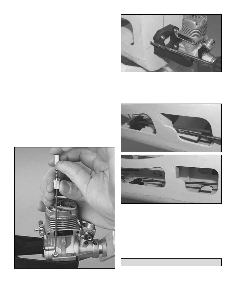
2. Temporarily attach the engine mount (inverted) to the firewall
with four 6-32 x 3/4" machine screws and #6 flat washers. Do
not tighten the screws all the way, because you still need to
adjust the mount.
❏
3. Place the engine on the mount and slide the halves in or
out until the engine fits properly. Position the mount so the
molded-in “tick marks” are equally spaced on the vertical
centerline you drew on the firewall. When the engine mount is
adjusted and positioned, tighten the mounting screws.
❏
4. Position the engine on the mount so the front of the drive
washer (or the back of the spinner) is 4-3/4" away from the
firewall and clamp in place.
❏
5. Use the Great Planes Dead Center
™
Engine Mount Hole
Locator (GPMP8130) to mark the locations of the bolt holes.
Remove the engine from the mount and drill four #36 (or 7/64")
holes. Tap the engine mount with a 6-32 tap for the 6/32 x 3/4"
machine screws.
❏
6. Select the 11-3/4" grey outer pushrod guide tube for the
throttle. Use coarse sandpaper to roughen the outside of the
tube so the glue will stick. Using the location of your particular
engine’s throttle arm as a guide, drill a 3/16" hole through the
firewall for the throttle pushrod guide tube. Slide the throttle
pushrod tube through the firewall.
❏
7. Position your throttle servo in the servo tray. Looking at the
left side of the inverted fuse, angle the pushrod tube so it will go
directly from the firewall to the servo arm, while keeping the
pushrod tube as close to the fuse side as possible. Drill a 3/16"
hole through F2 to match the angle and position of the pushrod
tube. Position and glue the pushrod tube flush with the front of
the firewall. Trim the excess pushrod tube 1/4" in front of the
servo tray.
Note: It is important that the throttle pushrod be
close to the fuse side to allow clearance for the tank.
❏
1. Temporarily mount the rudder to the fin with the hinges.
DO NOT GLUE. Mark the location of the tailgear wire on the
rudder and the nylon tailgear bearing on the fuselage, aligning
the nylon tailgear bearing touching the fuse bottom. Remove
the rudder.
Mount the Tailgear
28