Mount the wing to the fuselage – Great Planes Spitfire 40 Kit - GPMA0179 User Manual
Page 21
❏
2. Glue the die-cut 1/8" ply
former F2A to the front of die-cut
1/8" ply
former F2, aligning the dowel holes. Note: The embossed
labels on each former are on the front side.
❏
3. Position the die-cut 3/32" balsa
formers F5, and F4, then
the die-cut 1/8" ply
formers F3 and F2 into their notches in the
fuse top. Position the fuse sides inverted over the plan bottom
view, locking into the formers and the fuse top.
❏
4. Position the 1/8" die-cut ply
aft fuse bottom AFB between
the fuse sides and onto the formers. Checking that the fuse
sides are perpendicular to the work surface as you go, glue all
joints, working from the aft end of the fuse forward.
❏
5. Lift the fuselage off the plans. Carefully inspect all glue joints,
and reinforce any weak joints with medium CA on the inside of
the fuselage.
❏
6. Glue the two die-cut 1/8" ply
fuse supports FS in place
in the bottom corners of the fuse.
❏
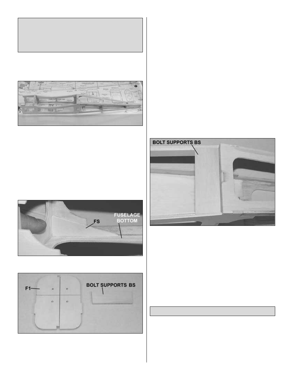
7.
Note: Refer to this photo for the following four steps.
Glue the two die-cut 1/8"
ply bolt supports BS together.
❏
8. Place one die-cut 1/8" ply
former F1 on the building board,
punch marks and embossing facing up. Epoxy the second F-1
to the first with 30-minute epoxy, again with the punch marks
facing up. Make sure the edges all the way around are aligned.
Wipe away excess epoxy before it cures. From now on this
assembly will be referred to as the
firewall. Note: If the formers
are warped, simply clamping them together may not “cancel
out” the warps. It is best to clamp the formers to a table or a flat
board until the epoxy cures.
❏
9. Using a straightedge, draw lines horizontally and vertically,
connecting the punch marks. The intersection of these two lines
is the center of the engine mount.
Note: This location is offset for the right thrust built into the model
so that the spinner will still align with the center of the cowl.
❏
10. Drill the four 11/64" (5/32" is OK) holes at the punch marks
as shown in the photo for the included Great Planes Engine
Mount. Press the four supplied 6-32 blind nuts into the holes on
the back of the firewall. Gently tap the blind nuts with a hammer
to fully seat them into the firewall, then add a few drops of thin
CA around the blind nuts to secure them. Take care not to get
any CA into the threads of the blind nut.
❏
11. Using 6-minute epoxy, position and glue BS into the wing
saddle, notched tight into both fuse doublers and against both
fuse sides.
❏
1. If necessary, sand the entire wing saddle area lightly until
the fuse side doublers and fuse sides are flush.
Note: Be
careful not to sand an angle into the wing saddle.
❏
2. Test fit the wing on the fuse. Center the wing side-to-side,
leaving equal space between the fuse sides and the wing at the
leading edge. If necessary, sand or trim the wing’s trailing edge
slightly to properly fit the wing saddle.
Mount the Wing to the Fuselage
DESIGNER’S NOTE: The 2° right thrust built into the firewall
helps keep the aircraft tracking straight under acceleration and
deceleration, minimizing the need to apply right rudder in
coordination with throttle. This design requires no down thrust.
The thrust angles built into this aircraft have been extensively
tested and we recommend you do not modify them.
21