Install the servos & make the pushrods – Great Planes Spitfire 40 Kit - GPMA0179 User Manual
Page 32
❏
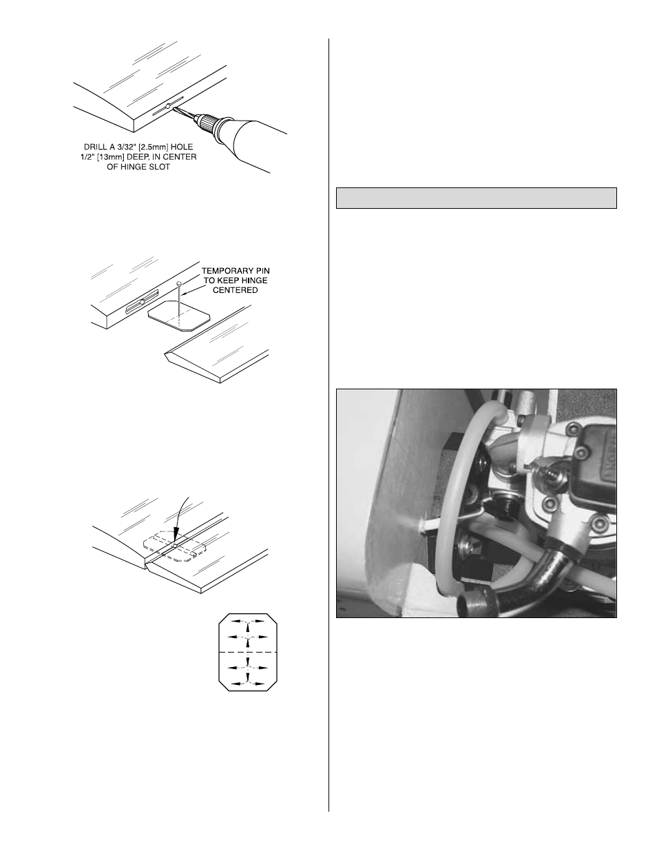
2. If you did not use a Slot Machine to make your hinge slots,
drill a 3/32" hole 1/2" deep in the center of each hinge slot. A
high speed Dremel Multi-Tool works best for this. If you use a
regular drill, clean out the hinge slots with a #11 blade.
❏
3. Without using any glue, fit the hinges in the elevators or
stab.
Do not glue the hinges yet. As you join the elevators to
the stab, confirm that the hinges are equally inserted in the
elevators and the stab. Insert a small pin in the center of the
hinges to keep them centered.
❏
4. Remove the pin and add 6 drops of thin CA to the center
of all the hinges on both the top and the bottom.
Do not use accelerator on any of the hinges. Do not glue
the hinges with anything but thin CA and do not attempt to
glue one half of the hinge at a time with medium or thick
CA. They will not be properly secured and the controls
could separate while the model is in flight.
❏
5. Prepare the hinge slots for the rudder as you did the
elevators. Join the rudder to the fin with the hinges and use
30-minute epoxy to simultaneously glue the tailgear wire in the
rudder and the tailgear bearing in the fuse.
Do not glue the
nylon bearing to the rudder. Glue the hinges in position with
thin CA.
Note: Petroleum jelly on the areas where the tailgear
bearing contacts the wire will ensure that it does not become
glued to the tailgear wire or rudder.
❏
6. Prepare the hinge slots in the ailerons the same way you
did for the tail surfaces. Glue the hinges with thin CA.
❏
1. Install a nylon clevis on the 17-1/2" throttle pushrod wire.
Slide the throttle pushrod through the pushrod tube with the
clevis on the servo end. Without attaching the clevis to the
servo, bend the pushrod as needed to make the pushrod move
smoothly and the clevis properly reach the servo arm.
❏
2. Bend and/or cut the engine end of the throttle pushrod as
needed to fit the engine installation. Make adjustments to the
bends in the wire so the pushrod aligns with the carburetor arm
on the engine. Slide a 2" piece of white pushrod inner over the
pushrod and glue it to the pushrod at the distance where the
pushrod exists the firewall.
Note: This plastic bearing will
minimize fuel running back down the pushrod tube.
❏
3. Temporarily connect the pushrod to the carb arm with
whatever connection type you have selected for the throttle.
(We recommend the simplicity of using a Z-bend.) Temporarily
mount the muffler and make sure the throttle pushrod will not
interfere with the muffler. Make adjustments to the bends in the
wire if necessary.
❏
4. Trim the covering from the pushrod openings in both sides
of the fuse.
❏
5. Slide the die-cut 1/8" ply
pushrod support over the servo ends
of the elevator and rudder pushrods. Do not glue it at this time.
❏
6. Screw a clevis onto one 35" pushrod wire (threaded on
both ends) for the rudder pushrod. Slide the pushrod wire
through the rudder pushrod guide tube, which is the guide tube
Install the Servos & Make the Pushrods
THE CA WICKS
ALONG THE "TUNNELS"
TO THE ENTIRE
HINGE SURFACE
ASSEMBLE, THEN APPLY 6 DROPS
OF THIN CA TO CENTER
OF HINGE, ON BOTH SIDES
32