Assemble the cowl – Great Planes Spitfire 40 Kit - GPMA0179 User Manual
Page 29
❏
2. Drill a 1/8" (or 7/64") hole 5/8" deep in the leading edge
of the rudder at the mark you made for the tailgear wire. Cut a
groove in the rudder for the nylon tailgear bearing (use a Great
Planes Groove Tube tool or a 5/32" brass tube sharpened at
one end to cut the groove). Test fit the tailgear wire in the rudder.
❏
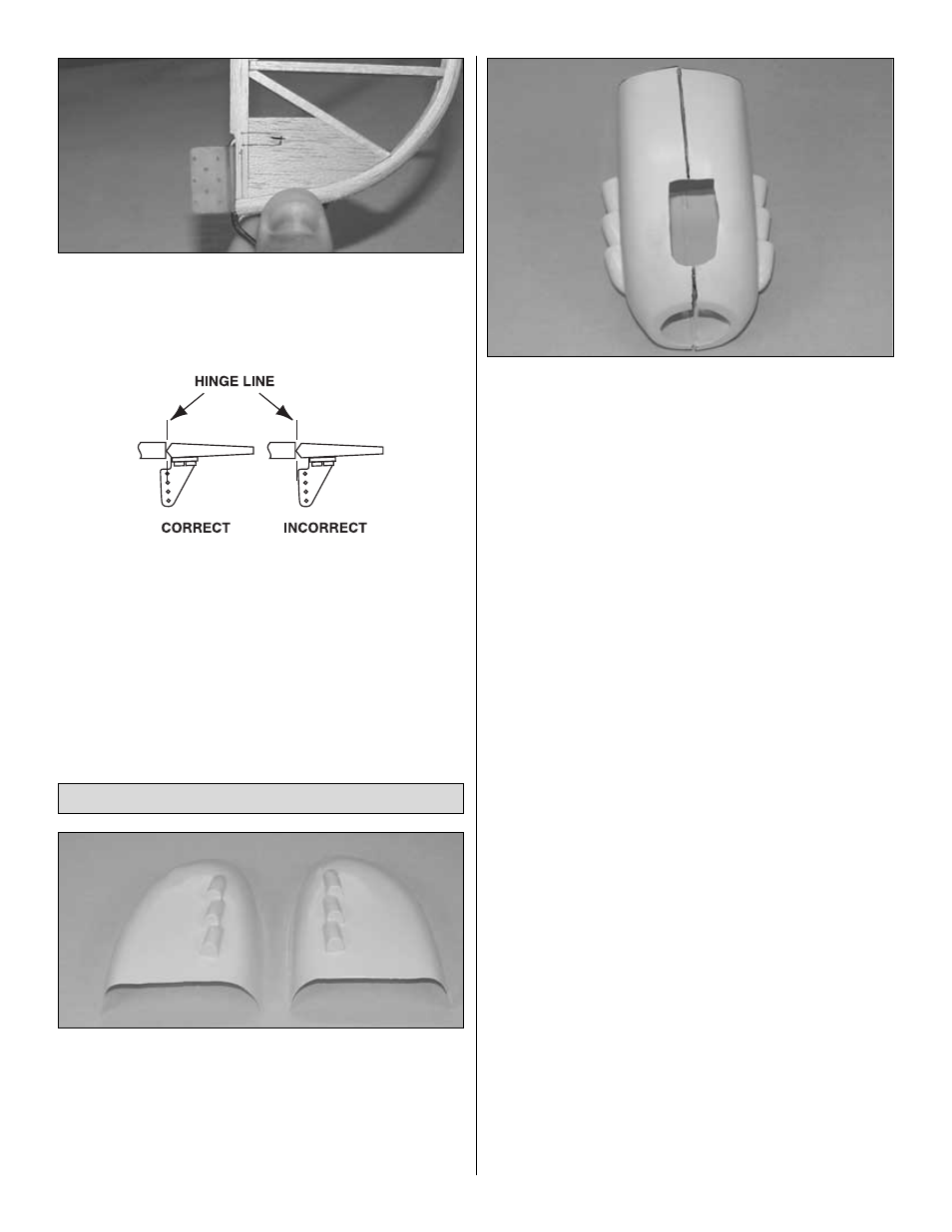
3. Position the control horn on the rudder as shown in the
sketch and on the plan. Use a ballpoint pen to mark the location
of the control horn mounting holes and drill 3/32" holes at the
marks. Temporarily mount the control horn to the rudder with
the backing plate and two 2-56 x 5/8" screws, trapping the
tailgear wire between the screws. Remove the control horn.
❏
4. Cut a slot in the trailing edge of the fuse at the marks you
made for the nylon tailgear bearing. Without using any glue, test
fit the rudder to the fin with the tailgear wire until there is no gap.
❏
1. Cut the cowl halves along the cutlines, then use a bar
sander with 80-grit sandpaper to true all the edges. To check
the straightness of the edges, set the cowl half on its seams on
the building board to be sure it is straight and smooth.
❏
2. For now, just rough cut the openings in the front of each
cowl half. Using coarse sandpaper, roughen 1/2" along the
overlaps of each cowl half so the glue will stick.
❏
3. Tape the two pieces together, using several pieces of masking
tape and taping across the seams. Note the overlap in the cowl halves.
❏
4. Test fit the cowl to the fuselage and adjust the taped seams
as needed for a proper fit. Carefully remove the cowl from the
fuselage.
Note: You may need to remove your engine’s needle
valve, exhaust and possibly even the head to test fit the cowl.
❏
5. Cut four 1" sections off the 1" x 18" fiberglass tape and
set aside for the cowl mounting screw locations. Secure the
inside of the cowl seams with the remaining fiberglass tape and
thin CA.
❏
6. Use a sharp hobby knife or a Dremel Multi-Tool with a sanding
drum to accurately cut the openings at the front of the cowl.
❏
7. Slide the cowl onto the fuselage. Slide the spinner backplate
over the crankshaft, moving the cowl as necessary to leave a
1/8" gap between spinner and cowl, and secure the backplate
in place. Position the cowl so that it aligns properly with the
spinner.
❏
8. Hold the cowl in position tight against the front deck
sheeting and aligned with the spinner. Drill the first cowl
mounting screw hole with a 1/16" drill bit. Screw in place with a
#2 x 3/8" screw.
❏
9. Confirming the proper positioning of the cowl before drilling
each hole, drill the remaining holes and install the remaining 3
screws one at a time.
❏
10. Remove the screws and the cowl from the model. Enlarge
the pilot holes you just made in the fuse with a 1/8" drill bit.
From the 6" piece of white pushrod inner, cut four 1/4" lengths,
making four
cowl screw retainers. Push the retainers into
each hole until flush with the fuselage side. Glue in place with
thin CA from the inside of the fuselage.
Note: These plastic
retainers help keep cowl screws from vibrating loose.
❏
11. Use a piece of thin cardboard or plastic to make a template
for the cutout in the cowl for the valve cover and mixture screw
of the engine, and for access for the glow plug heater. Tape the
template to the fuselage side, accurately indicating the
positions.
❏
12. Remount the cowl in position with the mounting screws,
being careful not to move or damage the paper template. Use
a felt-tip pen to transfer the holes in the template onto the cowl.
Assemble the Cowl
29