Great Planes Cherokee Kit - GPMA0180 User Manual
Page 27
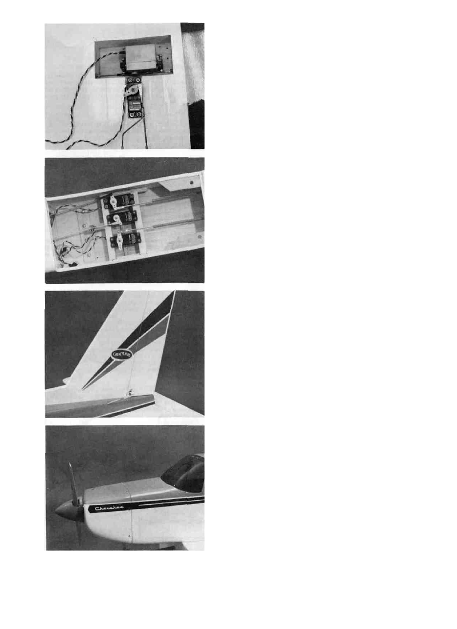
17. D INSTALL THE AILERON AND FLAP
LINKAGES AND SERVOS
Cut the servo well into the wing. Use Ply or balsa
and glue in sides and a floor. The flap servo may be
mounted sideways instead of as it is shown on the plan.
Whichever way you install it, cut away the smallest area in
the wing as possible. Install both servos as per radio manufacturers instructions. Usually there is a tray included
with the radio for the servos. Use the tray and mount the
servos to hardwood servo rails glued into the wing. Attach
wire pushrods soldered together to the flap torque rods
with nylon connector, wheel collars and screws provided.
Use a clevis of your choice for each torque arm. Attach the
linkage to the flap servo with a clevis also. Install the
aileron pushrods inside the housings and attach the aileron
servo arm to the wire with a connector of your choice such
as Dubro's Aileron Connector and Dual Take-Off Ball Link.
Attach the other end of the pushrod permanently to the
nylon bellcrank. Attach a wire pushrod permanently to the
bellcrank and run it from the bellcrank to the Aileron Horn.
Make this end adjustable at the horn.
18. D INSTALL THE FUSELAGE SERVOS
AND LINKAGES
Install the servos for the Rudder, Elevator and
Throttle/Steering linkages. Install the inner pushrods and
make one end adjustable with a connector of your
choice. Install the battery and receiver and switch. Run the
antenna out the Cabin Top and attach it to the Fin front. Do
not cut the antenna wire. Check the center of gravity and
move the battery and/or receiver to get the proper CG.
19. D APPLY THE DECALS
The Decals are mylar and are pressure sensitive.
Cut the decals apart from each other and select the ones
you need for the particular model you chose (use "Cherokee"
or "Cherokee Archer"). See the plan for the placement of the
decals. Put the decals in position and press them in place.
20. D INSTALL THE COWL, PROPELLER
AND SPINNER
Install the Cowl with the #4 x 5/8 Screws provided.
Install a 10-5 or 10-6 propeller. Install a 2 " Spinner.
21. D CHECK RADIO OPERATION AND CENTER
OF GRAVITY
The servos and linkages should not bind or inter-
fere with each other. Set the control surface throws as
follows:
1/2" up and down
3/4" down
Ailerons
Flaps
Elevators
Rudder
5/8" up and down
1" left and right
Re-check the Center of Gravity.
27