Great Planes Cherokee Kit - GPMA0180 User Manual
Page 26
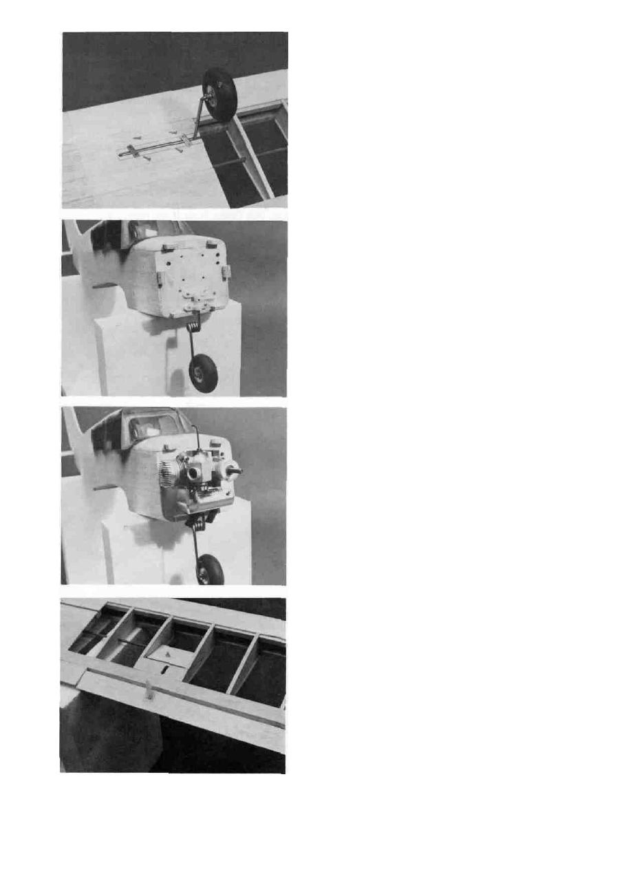
13. D INSTALL THE MAIN GEAR
Place the Wire Main Gear into the Landing Gear
Blocks in the underside of the Wing. Hold the Wire Gear in
with the metal Hold Down straps and sheet metal screws.
Use two straps on each gear. Drill pilot holes in the Blocks
first. Then put the screws in place.
14. D INSTALL THE NOSEGEAR AND FRONT WHEEL
Install the Steering Arm, Wheel Collar and Wire
Nosegear into the nylon bearing.
Note: The nosegear bearing is now one piece as shown on the
plan.
15. D INSTALL THE ENGINE AND MUFFLER
Attach the engine with self tapping screws or bolts
and lock nuts. To maintain the scale appearance of your
Cherokee, we recommend using a muffler that will be con-
tained inside the Cowl. The Tatone Pitts-style muffler
(number 11434 TT-60) will strap on the K&B 40 and OS 40
engines, and the exhaust will be pointed out the Cowl. A
few suggestions about installation: 1-lt might be helpful to
use a small jeweler's file to smooth the mounting face of
the muffler. Take care in filing - your objective is to get
the face as flat as possible. 2-Add a pressure tap fitting.
Your local dealer will probably stock several brands of
pressure fittings. We would suggest drilling the hole
centered in the front of the muffler. After tapping the hole
with the correct size tap, install pressure fitting using high
temperature epoxy or Loctite. 3-When installing the muf-
fler to the engine, (after engine is bolted in place), clean
the exhaust port of the engine and muffler with thinner and
add silicone to seal the muffler. Use silicone sparingly.
4-Depending on your choice of engines, exhaust port loca-
tion, muffler choice, etc., you may want to use black neo-
prene or silicone exhaust extensions to make sure the ex-
haust is routed out of the Cowl. Fasten the neoprene to
each exhaust tube using a nylon tie wrap. Cut the neo-
prene tube flush with the exterior shape of the Cowl to
maintain the scale look.
16. D PERMANENTLY INSTALL ALL CONTROL
SURFACES AND HORNS
Glue all the hinges in place. Lightly sand both sur-
faces of the hinges first, put epoxy (or gap filling CA) into
each slot and place the hinge in place. Use 2-56 screws
and backplate and attach the nylon Rudder Horn to the
Rudder. Inset the 1/16" Ply Plate on the bottom of the Ailer-
on at the nylon horn location. Attach the nylon horn to the
Ply Plate and Aileron with sheet metal screws. Shorten the
screws if necessary so they do not show on the top side of
the Aileron. Do not use the Back Plates on the Ailerons.
26