Get the model ready to fly apply the decals, Set the control throws – Great Planes 38% Extra 330S ARF - GPMA1290 User Manual
Page 20
20
❏
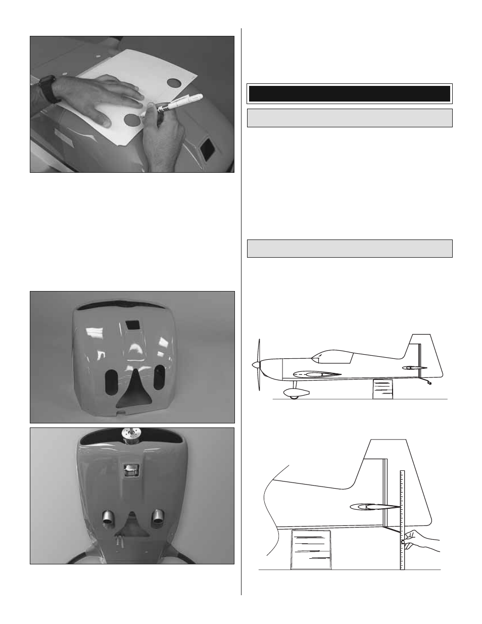
9. Remove the muffl ers. Mount the cowl to the fuselage.
Use a fi ne-point felt-tip pen to mark the holes for the exhaust
pipe cutouts directly onto the cowl.
❏
10. Remove the cowl. Use a rotary tool with cutting bits
to rough-cut the exhaust pipe holes in the cowl. CAUTION:
Always wear safety goggles, a particle mask and rubber
gloves when grinding, drilling and sanding fi berglass parts—
wearing a long-sleeve shirt and working outdoors is also a
good idea. Vacuum the parts and the work area thoroughly
after working with fi berglass parts.
❏
11. Remount the muffl ers. Fit the cowl to the fuselage
noting where the cowl must be trimmed to neatly fi t over
the exhaust pipes with plenty of clearance. Continue to cut
and mark the cowl as necessary until you can get it to fi t
over the pipes. Also make a generous cutout for cooling air
fl ow. Smooth the edges of all the holes you have cut with
400-grit sandpaper.
GET THE MODEL READY TO FLY
Apply the Decals
1. Use paper towels and window cleaner to wipe oily
fi ngerprints and dust from the model. Cut out the decals.
2. “Float” the decals into position by dipping them in a solution
of liquid dish soap and warm water—just a few drops of soap
per gallon of water.
3. Use a piece of soft balsa or something similar to squeegee
the water from under the decals.
Set the Control Throws
Perform the following procedures to measure and set the
control throws according to the measurements on page
21. The illustrations depict measuring elevator throw, but
the procedure is the same for measuring the ailerons and
rudder. Note: The throws are measured at the widest part
of each control surface.
❏
1. Use a small box or something similar to prop up the
fuselage until the wings and horizontal stab are level.
❏
2. With the surface centered, take the initial reading at the
widest part of the surface you are measuring.