Great Planes 38% Extra 330S ARF - GPMA1290 User Manual
Page 18
18
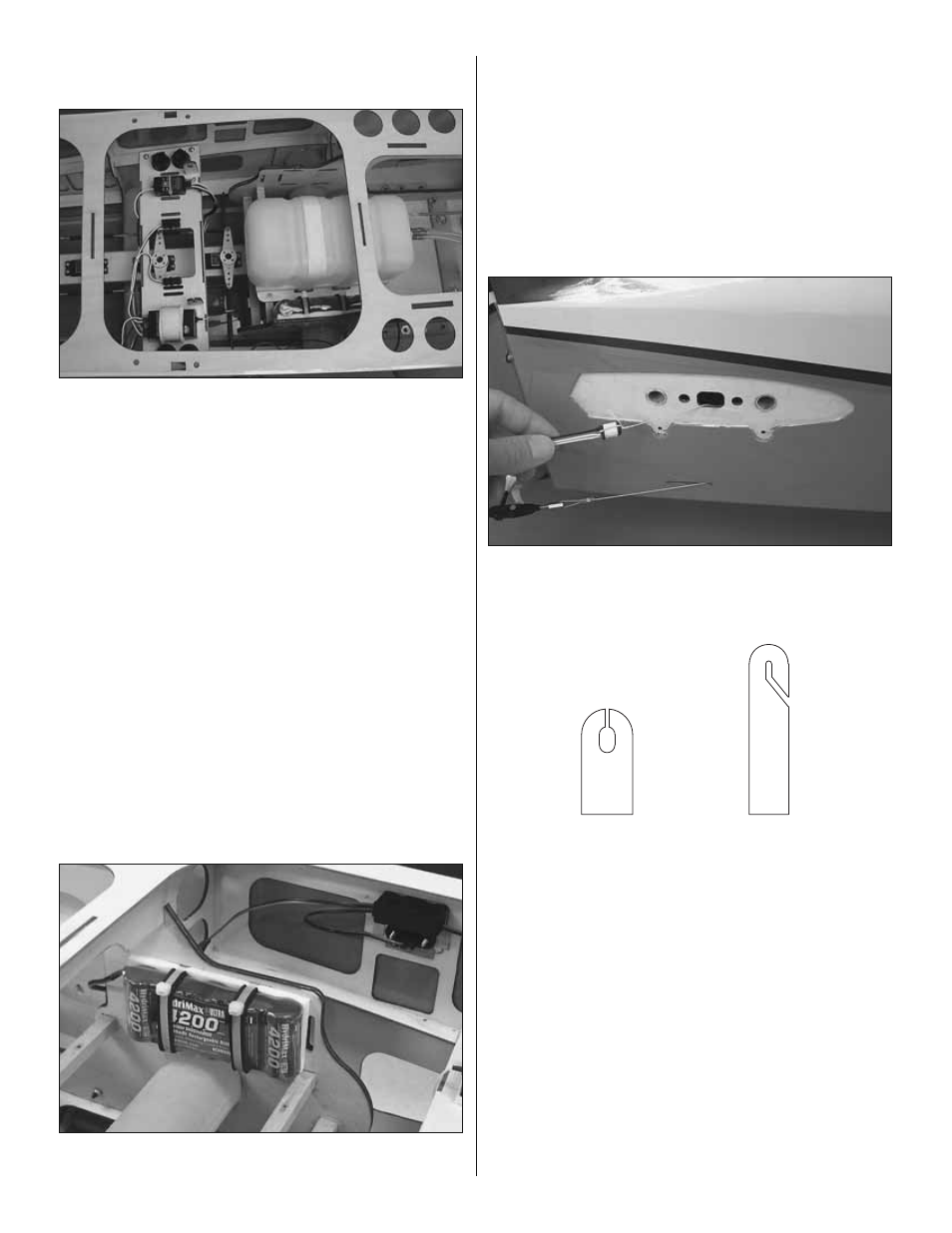
Refer to this photo while fi nishing
the rest of the radio installation.
❏
2. Glue the plywood receiver tray mount doublers to the
bottom of the side stringers—the hole in each doubler aligns
with each hole in the side stringer.
❏
3. Mount the receiver tray to the side stringers with four
#4 x 1/2" [13mm] screws and #4 washers—don’t forget to
remove the screws and the tray, apply a few drops of thin CA
in the screw holes and allow to harden. Remount the tray.
❏
4. Mount your receiver and servo synchronizer to the
receiver tray using straps from the included hook and loop
or nylon tie wraps (not included) and foam cushioning to
protect them from vibration. Guide the receiver antenna
down through the antenna tube in the fuselage.
❏
5. Connect the aileron servo extensions, the throttle servo
and rudder servo synchronizer to the receiver. As shown in
the photo, the dual servo extensions used were glued to the
receiver tray.
❏
6. Same as the on/off switch and charge receptacle were
mounted for the ignition battery, mount the on/off switch for
the receiver—the switch mounting holes are just ahead of
the receiver tray.
❏
7. Temporarily unscrew the fuel tank tray from the
mounting rails and move the tank forward. Use nylon tie
straps (not included) or the included hook and loop strap
material to mount the Rx battery to one of the sub fuselage
sides on either side of the fuselage as shown. Note the foam
wing tape (not included) used to keep the tie straps from
slipping. Secure the connections between the battery and
on/off switch and the switch and charge receptacle with heat
shrink tubing. Remount the fuel tank tray.
❏
8. Refer to the illustration on page 26 for the elevator servo
extensions. Make up the extensions for the way you will be
hooking up your servos.
❏
9. Pull the extensions down through the tube in the
fuselage and connect the elevator servos to the receiver.
Servo Wire Guide
Servo Wire Hanger
❏
10. After all the radio extensions, batteries, switches, etc.
have been installed, use the provided plywood servo wire
guides and servo wire hangers (or more J’Tec clamp loks)
to suspend or guide any servo wires out of the way that could
interfere with the rudder servos or anything else.
❏
11. Test fi t the canopy hatch with six 4-40 x 1/2" [13mm]
Phillips screws and #4 fl at washers. When ready to fl y the
model and mounting the canopy hatch at the fi eld, use
threadlocker on all the screws.