Hook up the rudder – Great Planes 38% Extra 330S ARF - GPMA1290 User Manual
Page 13
13
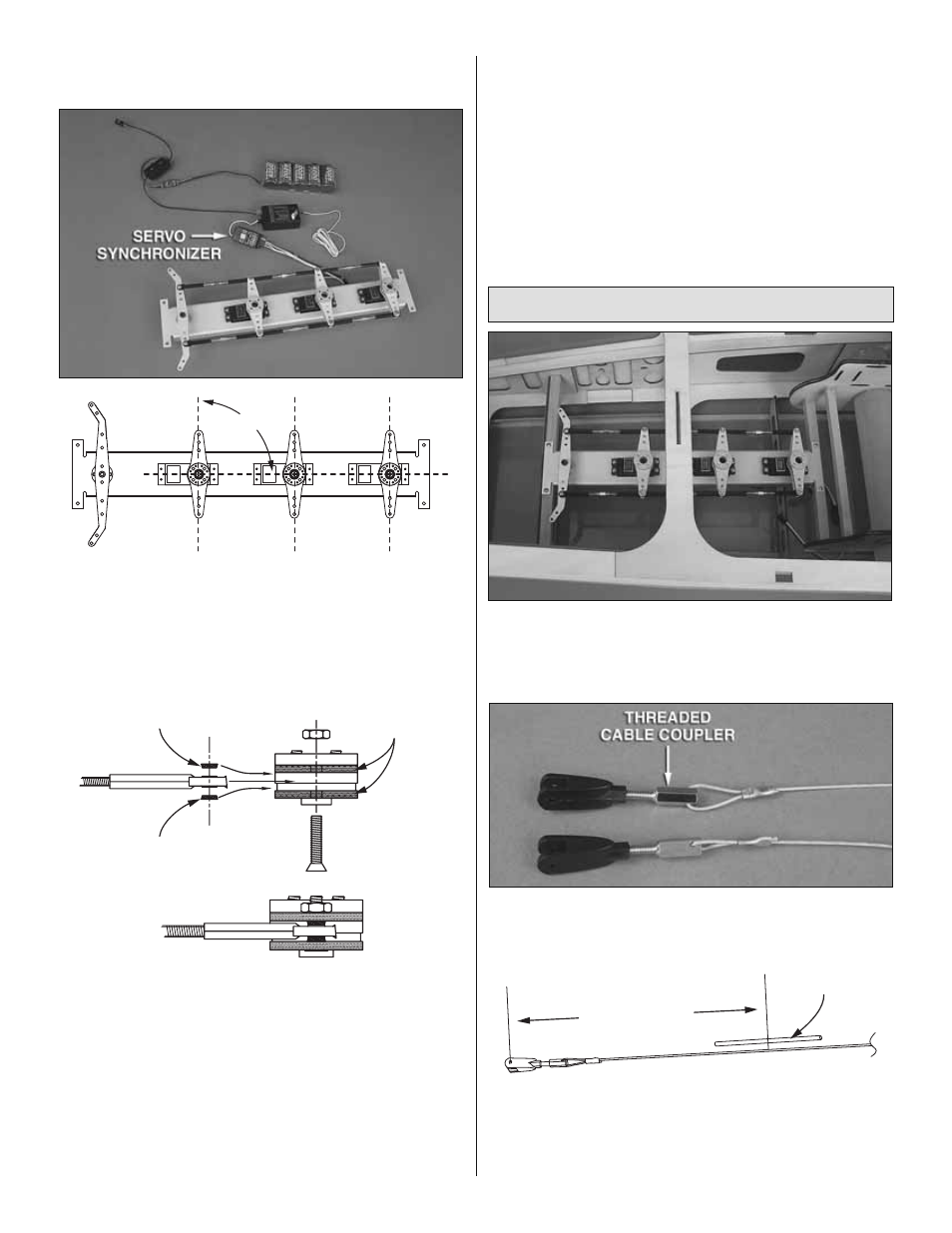
Refer to the following photo to fi nish
mounting the rudder servos.
90°
❏
5. Same as was done for the aileron and elevator servo
wheels, drill the holes in the three rudder servo wheels
with a 7/64" [2.8mm] (or 1/8" [3.2mm]) drill and mount the
double-sided servo arms to the servo wheels. Place the arm
assemblies on the servos and use a servo synchronizer to
center all the servo arms.
1mm Standoff
Double-Sided
Servo Arms
1mm Standoff
❏
6. Connect only the front of both rudder pushrods to the
front rudder servo arm using the same hardware that was
used to connect the aileron and elevator pushrods (that is
two 1mm brass standoffs, a 4-40 x 7/16" [11mm] fl at-head
Phillips screw and a 4-40 nut with threadlocker).
❏
7. Connect the pushrods to the middle rudder servo arm
using the servo synchronizer to align the holes in the arm with
the ball link balls in the pushrod. Using the servo synchronizer,
also make sure the servo arms are synchronized at the ends
of their throw.
❏
8. Connect the rudder pushrods to the aft rudder servo
using the synchronizer again. Don’t forget to use threadlocker
on the threads of all the screws.
❏
9. Finally, connect the last ball links on the end of the
rudder pushrods to the tiller arm with two 4-40 x 1/2" [12mm]
Phillips screws and 4-40 lock nuts.
❏
10. Secure the servo arm assemblies to the servos with the
servo wheel screws that came with the servos—if the screws
go into metal output shafts be certain to use threadlocker on
the threads.
Hook Up the Rudder
❏
1. Center the rudder servo tray assembly on the mounting
rails in the fuselage. Drill 3/32" [2.4mm] holes in the rails for the
mounting screws. Mount the tray with four #4 x 1/2" [13mm]
screws. Don’t forget to harden the screw holes with thin CA.
❏
2. Cut the braided rudder cable into two equal-lengths.
Make the aft end of both rudder cables from the hardware
shown (the “normal-thread” pin clevises are used here).
Shrink Tubing
22" [560mm]
❏
3. Cut the included 1/8" [3.2mm] diameter heat shrink
tubing into two equal lengths. Slide one tube over each cable
until the middle of each one is 22" [560mm] from the end of
the pin clevis. Shrink the tubing over the cables and glue it
into position with thin CA.