Mount the engine – Great Planes 38% Extra 330S ARF - GPMA1290 User Manual
Page 14
❏
4. Guide the cables through the slots in the fuselage and
temporarily connect the pin clevises to the horns on the rudder.
❏
5. Use masking tape to temporarily hold the front of the
balance tab on the rudder centered to the vertical stab.
Refer to this photo for steps 6 & 7.
❏
6. Mount a ball link with a threaded cable coupler to the
outer holes in both ends of the tiller arm with 4-40 x 1/2"
[12mm] Phillips screws, a 1mm standoff under each ball link
and 4-40 lock nuts.
❏
7. Cross the rudder cables once inside the fuselage—the
cable on the right side of the rudder should go to the left
side of the tiller arm and vice-versa. Slide a brass swage
over each cable. With the rudder servos connected to the
receiver and the radio on, loop one of the cables through one
of the threaded cable couplers on the tiller arm. Permanently
connect the cable to the cable coupler with the swage. Cut
off any excess wire.
❏
8. Connect the other cable to the cable coupler on the
other side of the tiller arm the same way.
❏
9. Remove the masking tape that was holding the rudder
centered. If necessary, adjust the tension in one or both
cables by removing the locking pin on the rudder and turning
one of the threaded inserts in or out. CAUTION: If, in the
future, the cables ever require tightening or loosening, always
disconnect one end of the cable you will be tightening
before turning the threaded couplers. This way, you will not
be twisting the cable (which could otherwise untwist). Never
twist the cables when tightening them.
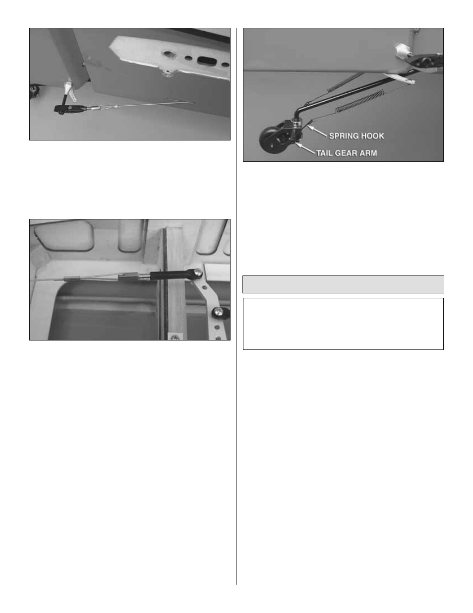
❏
10. Connect the tail wheel to the tail wheel arm on the
bottom of the rudder with the springs and spring hooks. Use
an .050" allen wrench to lock the spring hooks into the tail
gear arm with 4-40 set screws and a drop of threadlocker on
the threads. Center the tail wheel to the rudder by adjusting
the position of the spring hooks in the arm.
Mount the Engine
Instructions are provided for mounting the Desert
Aircraft 150cc engine. If using a different engine, use
the instructions as a guide. The centerlines on the
fi rewall note where the centerline of your engine should
be mounted so the spinner will align with the cowl.
❏
1. If mounting the DA 150, drill 1/8" [3.2mm] pilot holes
through the four crossmarks in the fi rewall for the engine
mounting bolts. If using a different engine, use the template
that came with your engine or take measurements from your
engine to mark the location of the engine mounting bolts,
and then drill the pilot holes.
❏
2. Enlarge the pilot holes in the fi rewall with a 19/64"
[7.5mm] (or 9/32" [7mm]) drill.
❏
3. Use a 3/16" Allen wrench to draw the blind nuts into the
back of the fi rewall with one of the included 1/4-20 x 2-1/2"
[60mm] SHCS and included aluminum engine spacers.
❏
4. Temporarily mount the engine to the fi rewall with the
spacers and the 1/4-20 x 2-1/2" [60mm] SHCS and 1/4"
[6.4mm] lock washers. (During assembly, you will probably end
up removing and remounting the engine a couple of times, so
no need to fully tighten the mounting bolts at this time.)
The ignition battery and ignition module will be mounted later.
14