Low voltage wiring – FloAire Electrical Controls User Manual
Page 9
A0023032
August 2014 Rev. 7
9
Low Voltage Wiring
Low voltage field wiring consists of Duct and Room Temperature sensors, ECM motors, 0-10VDC output,
24VDC input, or Modbus communication over CAT-5 cables for HMIs and remote equipment.
Additionally, panels can be ordered with Building Management Options. Refer to the Building
Management Owner’s Manual, if equipped, for low voltage building management wiring requirements.
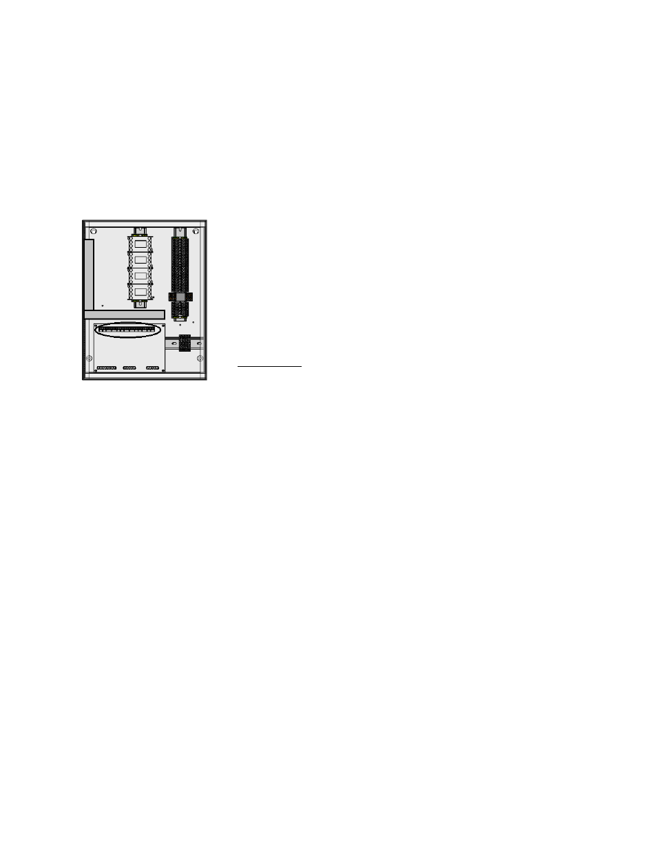
Low voltage wiring must be run through the wireway show below in the grey rectangle area. Wires will be
terminated on the terminals located on the ECPM03 board, circled below.
WARNING: Low voltage wires should never be run together with high voltage wires.
1- Room temperature sensor(s): For all installations utilizing duct
thermostats, at least 1 room temperature sensor must be installed in a
safe location, free of influence from external heat sources. It should be
indicative of the average kitchen temperature away from the appliances.
For packages with 2 separate fan zones, 1 or 2 room sensors can be
used. 2-wire 18 AWG thermistor cable must be used. The room
temperature sensor shall be wired according to the installation wiring
schematic, typically terminals “T1A”,”T1B”.
2- Duct temperature sensors: For all installations excluding a single
hood with factory risers and a hood mounted panel, duct mounted
temperature sensors will need to be wired in the field. 2-wire 18 AWG
plenum rated thermistor cable must be used. The temperature sensor
should be wired to terminal blocks as indicated on the installation wiring
schematic.
3- HMI(s) are connected to the ECPM03 board through CAT-5 cable. The HMI have two RJ-45
connectors connected together for Modbus.
a. If the panel was ordered with only 1 fan switch and/or 1 light switch, the HMI would connect
to port J4 (RJ-45) of the ECPM03 board. The other RJ-45 port of the HMI will typically be
occupied by a RJ-45 end-of-line terminator (Part # EOL120A).
b. If the panel was ordered and configured for 2 fan or 2 light switches, the first HMI would
connect to port J4 (RJ-45) of the ECPM03 board. The second HMI would connect to
ECPM03 board two ways:
o Connect the second HMI to the first HMI through CAT-5 cable. In this case the RJ-45
end-of-line terminator (Part # EOL120A) would only be used on the second HMI.
o Connect the second HMI to port J5 (RJ-45) of the ECPM03 Board. The other RJ-45
port of the HMI will typically be occupied by a RJ-45 end-of-line terminator (Part #
EOL120A).
4- Two end-of-line terminators (Part # EOL120A) are included in each panel. They are typically
plugged in at the factory on J3 and either on port J4 or in the back of the first HMI. If another HMI or
other equipment need to connect to a port occupied by an end-of-line terminator, it shall be removed
and place on the HMI or equipment that became connected at the end of the Modbus network.
NOTE: A third end-of-line terminator would be included with the package if the panel is ordered with 2
fan or 2 light switches. The extra end-of-line terminators will be mounted on the second HMI, if
decided to connect the HMI to J5. Otherwise, if daisy chained both HMIs, the third-end-line terminator
should be mounted on J5.
5- If other pieces of equipment such as PCU Advanced Filter Monitoring (AFM) are connected to this
panel, a cat-5 cable will also be used to run the Modbus communication between these devices. The
cable would be plugged in port J3 of the ECPM03 board. The end-of-line terminators should then be
relocated from J3 to the empty RJ45 port of the PCU AFM module.