FloAire Electrical Controls User Manual
Page 26
A0023032
August 2014 Rev. 7
26
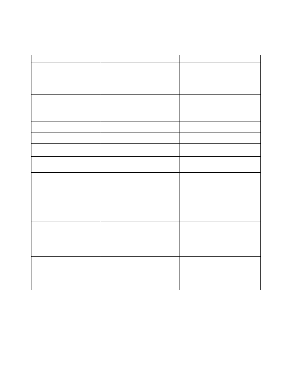
The following table lists Fault messages displayed on the HMI and corrective actions. Review this list prior
to consulting manufacturer.
Fault Message on HMI
Potential Cause
Corrective Action
“Fire”
FIRE or fire circuit not wired
properly.
If no fire, verify connection between
terminal blocks C1 and AR1.
“Equipment Disable
High Temp”
Duct temperature exceeded the
High Temp Equipment shutdown
Threshold and shut down the gas
valve and energizes the shunt trip.
Verify why Temp in duct is high.
Verify the Threshold value under
Configuration is set sufficiently high
(250 deg default).
“Light Fault Zone x
Bx De-
energized”
(x=1 or 2)
Light output is energized but no
power is detected on terminal Bx.
Verify that the light relay is not
damaged and that the light circuit
breaker is not tripped.
“Light Fault Zone x
Bx energized
” (x=1 or 2)
Light output is de-energized but
power is detected on terminal Bx.
Verify that the light relay contact is
not welded in the close position.
“Overload Trip
Zone
x” (x=1 or 2)
One of the overload relays for fans
associated with zone x is tripped.
Reset overload relay. Monitor fan to
see why overload tripped.
“Surfactant Low”
Surfactant level is low.
Refill Surfactant into the tank. Refer
to Self-Cleaning or CORE manual.
“PCU Fault”
PCU filters are clogged or missing.
Verify PCU filters and replace if
needed.
“Proving Fault”
Fan Proving Interlock enabled.
Exhaust fan not meeting its
minimum calibrated load.
Verify fans are running properly.
Verify Fan Proving calibration. Refer
to Fan Proving Interlock section.
“Fuse F1 Blown”
Fuse F1 is blown or missing
Replace fuse and verify there is no
short-circuit and load is below 4
amps.
“Temp Sensor x
Not Connected
”
Temperature sensor x is not wired
to the ECPM03 board.
Verify proper wiring to terminals TxA
and TxB on the board and wiring to
the sensor.
“Modbus Communication
Fault
”
One or several components on the
Modbus network are not
responding.
Verify HMIs are all plugged in. Verify
CORE or PCU AFM are plugged in if
configured as such.
“CORE x Fault”
Fault description
Specific fault is present on the
CORE fire system
Refer to the CORE manual for
specific fault description.
“PCU x Fault”
Fault description
Specific fault is present on the PCU
AFM x connected to the system.
Refer to the PCU AFM manual for
specific fault description.
“Temp Sensor x
Bad Sensor”
Bad Temp Sensor due to
overheating or internal failure
Replace the Temperature Sensor
“Communications fault
Check Configuration”
ECPM03 board and HMI not
communicating due to:
Software incompatible
Switchplate # doesn’t
match number of zones
Re-flash the HMI
Change switchplate #
Replace cat5 cable
Replace EOL