High voltage wiring, Electrical – FloAire Electrical Controls User Manual
Page 8
A0023032
August 2014 Rev. 7
8
Copper Wire Ampacity
Wire Size AWG
Maximum Amps
14
15
12
20
10
30
8
50
6
65
4
85
Electrical
Before connecting power to the control, read and understand
this entire document. As-built wiring diagrams are furnished
with each control by the factory and are attached either to the
door of the unit or provided within a paperwork pouch internal
to the panel.
Electrical wiring and connections should be done in
accordance with local ordinances and the National Electric
Code, ANSI/NFPA70. Be sure the voltage and phase of the
power supply and the wire amperage capacity is in accordance
with the unit nameplate.
1. Always disconnect power before working on or near
this equipment. Lock and tag the disconnect switch or
breaker to prevent accidental power up.
2. Make certain that the power source is compatible with
the requirements of your equipment. The installation
wiring schematic identifies the proper phase and
voltage of the source breakers.
3. Before connecting control to power source, verify
power line wiring is de-energized.
4. Secure all wiring to prevent contact with sharp objects.
5. Do not kink power cable and never allow the cable to come in contact with oil, grease, hot
surfaces or chemicals.
6. Before powering up the system, make sure that the interior of the control is free of loose debris,
metal shavings, or shipping materials. `
7. If any of the original wire supplied with the system must be replaced, it must be replaced with type
THHN wire or equivalent.
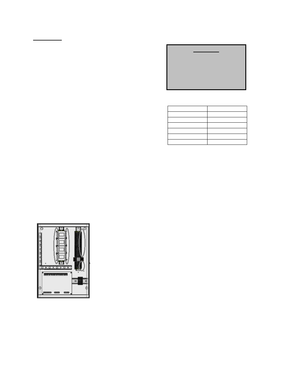
High Voltage Wiring
1. All high voltage wiring shall be terminated on the right side of the
terminal blocks or directly on the starters as designated in the
circled areas on the left hand diagram.
2. There are multiple electrical connections required for this
control. 120VAC should be wired to terminals H1 and N1. Input
power to the motors should be wired to
“L” series terminals. Motor
output power should be connected to
“T” terminals on the starters.
3. The hood light wiring will also need to be wired to terminals as
indicated on the installation diagram.
4. If an ANSUL fire system is present, the fire system micro-switch will
need to be wired to terminals as indicated on the installation
diagram, typically
“C1”, “AR1”. C1 is the common and connects to
terminal 1 on the micro-switch. AR1 is the armed state and
connects to terminal 2 on the micro-switch. If a CORE fire system is
present, this connection is not required.
WARNING!!
Disconnect
power
before
installing or servicing control.
High voltage electrical input is
needed for this equipment. This
work should be performed by a
qualified electrician.