Ecpm03 board – FloAire Electrical Controls User Manual
Page 24
A0023032
August 2014 Rev. 7
24
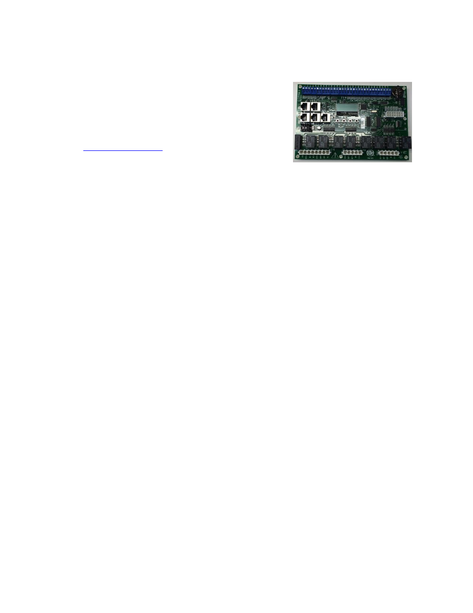
ECPM03 board
The ECPM03 is the main brain of the system. It receives all the digital and analog inputs, delivers the
digital outputs, and sends out messages to other devices.
Connector Descriptions
J1, J2: Modbus slave network connectors feed through
RJ45s, which conform to the Modbus pin out for RS485 2
wire differential Modbus RTU standard. See
Modbus communication is not
configured for third party integration without additional
components.
J3, J4, J5: Modbus master network connectors, feed through RJ45s, which conform to the
Modbus pin out for RS485 2 wire differential Modbus RTU standard. J4 or J5 are the only RJ45
port on the ECPM03 which serves as a power source for HMI(s).
J6 Factory low voltage connections
o Pin 1 positive side of the 24 Volt DC input to the board
o Pin 2
– 7 Open collector outputs, 100ma max each, suitable for driving 24VDC relays or
indicator lamps.
o Pin 8
– 12 4-20ma current inputs. 150 Ohm impedance to 24 VDC ground pin 14.
o Pin 13 Chassis ground connection, this pin connects to the 24VDC ground through a
paralleled 1000pf 2000V cap and a 100k Ohm 1/4W resistor.
o Pin 14 negative side of the 24 volt DC power input (ground or common side of the low
voltage circuitry)
J7: 120 VAC control connector for factory wiring
o Pin 1 IO1, BMS input, can detect the presence of 120VAC, this forces the fans on.
o Pin 2 B1, input, this pin can detect the presence of 120VAC
o Pin 3 EF1, output and input, this pin can source 120VAC and detect the presence of
120VAC
o Pin 4, SF1, output, this pin can source 120VAC
o Pin 5, OV1, input, this pin can detect the presence of 120VAC
J8: 120 VAC control connector for factory wiring
o Pin 1 IO2, output and input, this pin can source 120VAC and detect the presence of
120VAC
o Pin 2 B2, input, this pin can detect the presence of 120VAC
o Pin 3 EF2, output and input, this pin can source 120VAC and detect the presence of
120VAC
o Pin 4, SF2, output, this pin can source 120VAC
o Pin 5, OV2, input, this pin can detect the presence of 120VAC
J9: 120 VAC control connector for factory wiring
o Pin 1 N1, Neutral, this is the neutral or return path for the detection of 120VAC by the
input pins. It would be connected to the Neutral side of the 120 VAC supply
o Pin 2 AR1, input, this pin can detect the presence of 120VAC
o Pin 3 GAS, output, this pin can source 120VAC
o Pin 4 KTS, input, this pin can detect the presence of 120VAC
o Pin 5 KS, output, this pin can source 120VAC
o Pin 6 ST, output, this pin can source 120VAC
o Pin 7 PCU, input, this pin can detect the presence of 120VAC
o Pin 8 H1, this is the 120 Volt AC 50/60Hz input to the board, it feeds through an on board
4 Amp Slo-Blo fuse and is used to source 120 VAC to all the pins described as 120 VAC
outputs. The total current draw of all the 120VAC outputs must not exceed 4Amps.