Configuration parameters table – EVCO EC4173 User Manual
Page 5
5
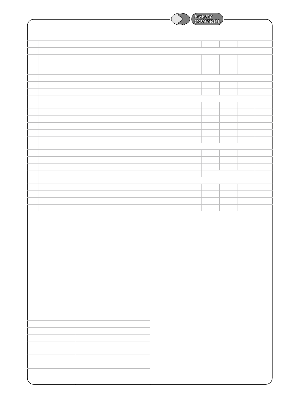
PRODUCTS LINE '96
CODE PARAMETER
DESCRIPTION
MIN.
MAX.
U.M.
ST.
(1)
PA
Password
-99
100
----
----
/
PROBE
/0
kind of probe
10="J" TC; 11="K" TC
10
11
----
*
(1)
/1
calibration (measure offset)
-10
+10
°
C
0
/2
digital filter (speed response) 0=0s; 1=0,4s; 2=1,2s; 3=2,8s; 4=6,0s; 5=12,4s; 6=25,2s
0
6
----
3
r
TEMPERATURE REGULATOR
r1
minimum setpoint admitted
0
+999
°
C
0
r2
maximum setpoint admitted
0
+999
°
C
(2)
P
P.I.D. REGULATOR
P0
offset band
-99
+99
°
C
0
PI
integral time
0
999
sec.
100
P2
Auto-tuning enabling
0=NO; 1=YES
0
1
----
1
Pb
proportional band
+1
+250
°
C
+30
Pc
P.I.D. cycle time
1
120
sec.
30
Pd
derivative time
0
250
sec.
35
A
ALARM
A0
alarm hysteresis (differential)
+1
+99
°
C
+1
A1
alarm setpoint
-99
+999
°
C
0
A3
alarm disabling time since instrument power-on
0
999
min.
0
A4
alarm mode
see TABLE
1
L
NETWORK CONNECTION
L1
instrument address
1
15
----
1
L2
instrument group
0
7
----
0
L3
time-out link
2
250
sec.
7
L4
baud rate
0
3
baud
1
CONFIGURATION PARAMETERS
TABLE
parameter A4
alarm mode
1
disabled
2
absolute minimum alarm
3
absolute maximum alarm
4
minimum alarm relative to setpoint
5
maximum alarm relative to setpoint
6
minimum alarm relative to setpoint
with automatic enabling and recompute
7
maximum alarm relative to setpoint
with automatic enabling and recompute
NOTES
(*) = depends on the kind of probe.
(1) = configuration parameter present on Level 1.
(2) = for "J" thermocouples r2 = 700 °C; for "K" thermocouples r2 = 999 °C.