EVCO EK354AJ7 User Manual
Page 3
Every Contr
ol S.r
.l. • EK 354A • Sheet 2/2
9
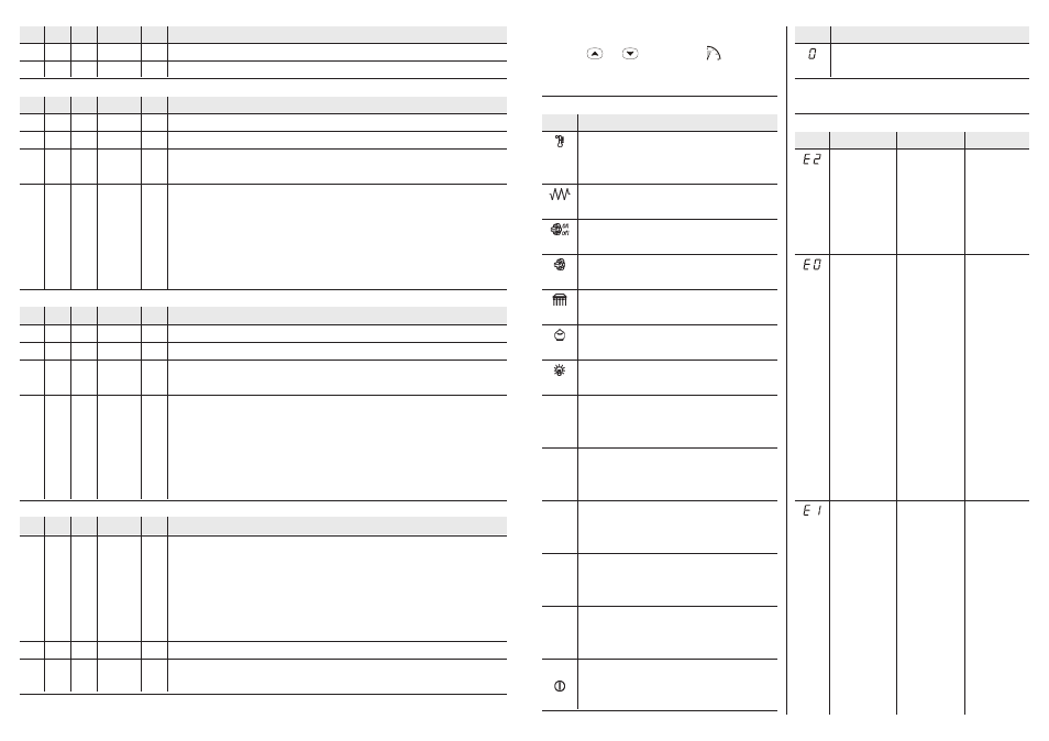
ALARMS
9.1
Alarms
CODE
corrupted
memory
data
alarm
chamber
probe
alarm
steam
probe
alarm (by
request)
REASONS
there is a corruption of
the configuration data
in the memory of the
instrument
• the kind of chamber
probe you have con-
nected is not right
• the chamber probe
plays up
• the connection in-
strument-chamber
probe is wrong
• the temperature the
chamber probe is
reading is outside
the limits allowed by
the working range
of the instrument
• the kind of steam
probe you have con-
nected is not right
• the steam probe
plays up
• the connection in-
s t r u m e n t - s t e a m
probe is wrong
REMEDIES
turn OFF the power
supply of the instru-
ment: unless the alarm
disappears, you will
have to change the
instrument
• look at parameter
/0
• test the integrity of
the probe
• test connection in-
strument-probe
• test the tempera-
ture close to the
probe
• look at parameter
/0
• test the integrity of
the probe
• test connection in-
strument-probe
• test the tempera-
ture close to the
probe
EFFECTS
• the access to the
setting procedures
will not be allowed
• all outputs will be
turned OFF
• the top output will
be turned OFF
• the floor output will
be turned OFF
• the steam genera-
tor will be turned
O F F
• the steam injection
will not be allowed
MEANING
the instrument has finished counting the cooking timer
To quit the procedure:
• press
and
for 4 s
or do not oper-
ate for about 60 s.
8
SIGNALS
8.1
Signals
LABEL MIN. MAX. U.M.
DEF. STEAM INJECTION
tb0
1
255
s
1
minimum time between two steam injections in succession
tb1
1
255
ds
(10)
10
minimum length of the steam injection
LABEL MIN. MAX. U.M.
DEF. FIRST ALARM
AA0
1
99
°C/°F
(8)
2
hysteresis (differential, it is relative to AA1, it is important if AA4 ≠ 1)
AA1
-99
999
°C/°F
(8)
0
first temperature alarm threshold (it is important if AA4 ≠ 1); look at AA4 as well
AA3
0
999
min
0
first temperature alarm exclusion time since you turn the instrument ON (it is important if
AA4 ≠ 1)
AA4
1
7
---
1
kind of temperature alarm (1 = it will never be activated, 2 = absolute lower temperature
alarm, 3 = absolute upper temperature alarm, 4 = lower temperature alarm relative to the
working setpoint, 5 = upper temperature alarm relative to the working setpoint,
6 = lower temperature alarm relative to the working setpoint with automatic calculation and
enabling, 7 = upper temperature alarm relative to the working setpoint with automatic
calculation and enabling)
LABEL MIN. MAX. U.M.
DEF. SECOND ALARM
Ab0
1
99
°C/°F
(8)
2
hysteresis (differential, it is relative to Ab1, it is important if Ab4 ≠ 1)
Ab1
-99
999
°C/°F
(8)
0
second temperature alarm threshold (it is important if Ab4 ≠ 1); look at Ab4 as well
Ab3
0
999
min
0
second temperature alarm exclusion time since you turn the instrument ON (it is important
if Ab4 ≠ 1)
Ab4
1
7
---
1
kind of temperature alarm (1 = it will never be activated, 2 = absolute lower temperature
alarm, 3 = absolute upper temperature alarm, 4 = lower temperature alarm relative to the
working setpoint, 5 = upper temperature alarm relative to the working setpoint,
6 = lower temperature alarm relative to the working setpoint with automatic calculation and
enabling, 7 = upper temperature alarm relative to the working setpoint with automatic
calculation and enabling)
LABEL MIN. MAX. U.M.
DEF. POWER/COOKING TIMER
c0
0
2
---
0
connection between the percentages of power supplied to the heating groups
(0 = no connection, 1 = the modification of the percentage of power supplied to a heating
group will automatically provoke the supply of the maximum power to the other one and vice
versa, 2 = the modification of the percentage of power supplied to a heating group will
automatically provoke an adjustment of the other one such as to guarantee that the sum of
bars turned ON will always be 10)
c1
1
999
s
80
cycle time to turn ON the top output and the floor output during the normal operation
c4
-1
120
s
5
time the buzzer is activated at the end of the cooking timer (-1 = the buzzer has to be silenced
by hand)
LED
°
C
°
F
h
min
start
MEANING
LED regulator
if it is lit, the temperature the chamber probe is reading is below the
working setpoint
LED top and floor
if they are lit, the top output and the floor output will be turned ON
LED steam generator
if it is lit, the steam generator will be turned ON
LED steam injector
if it is lit, the steam injection will be running
LED extractor
if it is lit, the extractor will be turned ON
LED economy
if it is lit, function Economy will be activated
LED chamber light
if it is lit, the chamber light will be lit
LED Celsius degree
if it is lit, the unit of measure of the temperature showed by the instru-
ment will be Celsius degree
LED Fahrenheit degree
if it is lit, the unit of measure of the temperature showed by the instru-
ment will be Fahrenheit degree
LED hour
if it is lit, the unit of measure of the time showed by the instrument will
be hour
LED minute
if it is lit, the unit of measure of the time showed by the instrument will
be minute
LED timer
if it flashes, the count of the timer for delayed starting (or the count of
the cooking timer) will be running
LED ON STAND-BY
if it is lit, the instrument will be in the STAND-BY mode (turned OFF)
INDICAT.