EVCO EV9336J9 User Manual
Ev9336
Evco S.p.A. • Code 1049336E00 • page 1/8
EV9336
Digital controller with 6 outputs for electric bread ovens, with RTC functions, programmed switch-
on, cooking timer, economy, rapid heating and programs management functions
version 3.00
GB ENGLISH
1
IMPORTANT
1.1
Important
Read these instructions carefully before installation and use and fol-
low all warnings regarding installation and for the electric connec-
tion. Keep these instructions with the instrument for future reference.
The instrument must be disposed of in compliance with
local Standards relative to the collection of electrical and
electronic appliances.
1.2
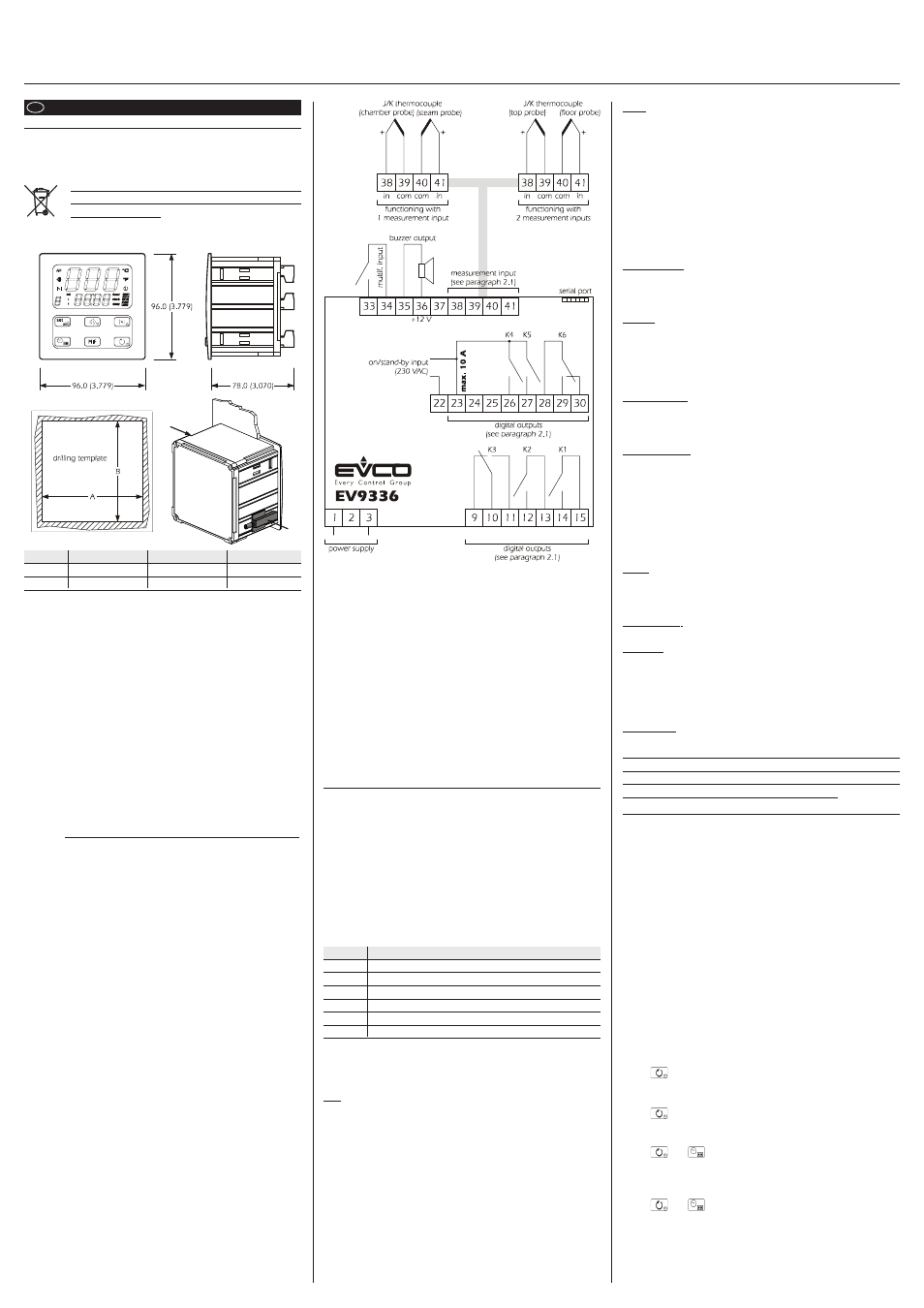
Dimensions and installation
Panel with supplied brackets with screws; dimensions in mm (in).
DIMENS.
MINIMUM
TYPICAL
MAXIMUM
A
92.0 (3.622)
92.0 (3.622)
92.8 (3.653)
B
92.0 (3.622)
92.0 (3.622)
92.8 (3.653)
Installation recommendations:
• the thickness of the panel must not exceed 4.0 mm (0.157 in)
• position the brackets as indicated in the drawing in this paragraph,
moderate the coupling torque
• make sure that the working conditions (temperature of use, humid-
ity, etc.) lie within the limits indicated in the technical data
• do not install the instrument in proximity of heat sources (resistances,
hot air pipes, etc.), appliances with strong magnets (large diffusers,
etc.), places subject to direct sunlight, rain, humidity, excessive dust,
mechanical vibrations or jerks
• in compliance with Safety Standards, protection against any contact
with electrical parts must be assured via correct installation of the
instrument. All parts that ensure protection must be fixed in a way
that they cannot be removed without the aid of a tool.
1.3
Electric connection
With reference to the wiring diagram: the serial port is the communi-
cation port with the supervising system (through a serial interface, via
TTL, with MODBUS communication protocol) or with the program-
ming key; the port must not be used for two purposes at the same time.
Recommendations for the electric connection:
• do not operate on the terminal boards using electric or pneumatic
screwdrivers
• if the instrument has been taken from a cold place to a hot place, the
humidity could condense inside; wait for about one hour before
applying power
• check that the power supply voltage, the frequency and the electric
operational power of the instrument correspond with those of the
local power supply
• disconnect the power supply before performing any type of main-
tenance
• supply the probes with protection able to isolate them from any
contact with metal parts or use isolated probes
• do not use the instrument as a safety device
• for repairs and information regarding the instrument, contact the
Evco sales network.
2
PRELIMINARY CONSIDERATIONS
2.1
Preliminary considerations
The instrument can be configured to function with 1 measurement
input (chamber probe) or with 2 measurement inputs (top probe and
floor probe). If functioning with 1 measurement input it is however
possible to enable a second probe (steam probe) to subordinate the
injection of steam at the temperature of the same.
Functioning with 1 measurement input allows to independently set
the power distributed to the top to that distributed to the floor. Func-
tioning with 2 measurement inputs allows to independently set the
top and floor work temperatures.
The utilities managed by the digital outputs (i.e. relays K1 ... K6) are the
following:
RELAY MANAGED UTILITY
K1
top
K2
floor
K3
can be set (default chamber light)
K4
airhole
K5
steam injection
K6
can be set (default steam generator)
To set the type of functioning (with 1 measurement input rather than
2) see paragraph 4.1. However, to set the utility managed by relay K3
and relay K6 see paragraph 4.2.
2.2
Management of the utilities
Top.
If functioning with 1 measurement input:
• the output is switched on in cyclical mode, preferably when the
floor output is off (the parameter c1 establishes the cycle time. The
procedure given in paragraph 4.5 can be used to set the duration
of output switch-on, intended as a percentage of the time estab-
lished with parameter c1)
• the cyclical activity is subject to the chamber temperature (chamber
probe), to the work set-point and parameter r0.
If functioning with 2 measurement inputs:
• the output activity depends mainly on the top temperature (top
probe), the top set-point and parameter r0.
Floor.
If functioning with 1 measurement input:
• the output is switched on in cyclical mode, preferably when the top
output is off (the parameter c1 establishes the cycle time. The proce-
dure given in paragraph 4.5 can be used to set the duration of
output switch-on, intended as a percentage of the time established
with parameter c1)
• the cyclical activity is subject to the chamber temperature (chamber
probe), to the work set-point and parameter r0.
If functioning with 2 measurement inputs:
• the output activity depends mainly on the floor temperature (floor
probe), the floor set-point and parameter r6
Chamber light.
The output is activated in manual mode.
Through the multifunction input it is also possible to activate the out-
put in remote mode.
Airhole.
The output is activated in the following conditions:
• before the conclusion of the cooking timer count (of the time estab-
lished with the parameter c5), for the time established with param-
eter c6
• in manual mode, for the time established for parameter c7.
Steam injection.
The output activity depends mainly on parameter t0.
Through the multifunction input it is also possible to activate the out-
put in remote mode.
Steam generator.
If functioning with 1 measurement input:
• if the steam probe is not enabled, the output is activated in manual
mode
• if the steam probe is enabled, the output is enabled in manual mode,
after which the activity of the same will depend on the temperature
of the steam (steam probe), the steam set-point and parameter t3.
If functioning with 2 measurement inputs, the output is activated in
manual mode.
Alarm.
The output is activated during a temperature alarm.
Through the multifunction input it is also possible to activate the out-
put in remote mode.
Cooking timer.
The output is activated during the cooking timer count.
Acoustics.
The output is activated in the following conditions:
• before the conclusion of the cooking timer count (of the time estab-
lished with the parameter c9), for the time established with param-
eter c4
• during an alarm or an error, with continuous contribution.
On/Stand-by.
The output is activated during the “on” state (see paragraph 3.1).
In spite of the fact that the instrument can manage the 10
utilities stated in this paragraph, there are 6 digital out-
puts available. Make sure that the desired utility is man-
aged by the instrument (see paragraph 2.1).
3
USER INTERFACE
3.1
Preliminary considerations
The following functioning states exist:
• the “on” state (the instrument is powered and on: the regulators can
be on)
• the “programmed switch-on” state (the instrument is powered but
switched off via software: the regulators are off and programmed
switch-on of the instrument is envisioned)
• the “stand-by” state (the instrument is powered but switched off via
software: the regulators are off and programmed switch-on of the
instrument is not envisioned)
• the “off” state (the instrument is not powered).
Successively, the term “switch-on” means the passage from the stand-
by state to the on state. The term “switch-off” means the passage from
the on state to the stand-by state.
When powered, the instrument re-proposes the state that it was in
when the power supply was disconnected.
3.2
Selecting the functioning state
To pass from the stand-by state to the on state (and vice versa):
• make sure no procedure is in progress
• press
for 1s.
To pass from the programmed switch-on state to the on state:
• make sure no procedure is in progress
• press
for 1s.
To pass from the on state to the programmed switch-on state:
• make sure no procedure is in progress
• press
and
for 1s.
To pass from the stand-by state to the programmed switch-on state
(and vice versa):
• make sure no procedure is in progress
• press
and
for 1s.
Through the on/stand-by input it is also possible to pass from the on
state (or from the programmed switch-on state) to the stand-by state in
remote mode.