Antifreeze, Cooling tower/boiler systems, Operation power up mode – Carrier AQUAZONE 50VQP084-300 User Manual
Page 36
36
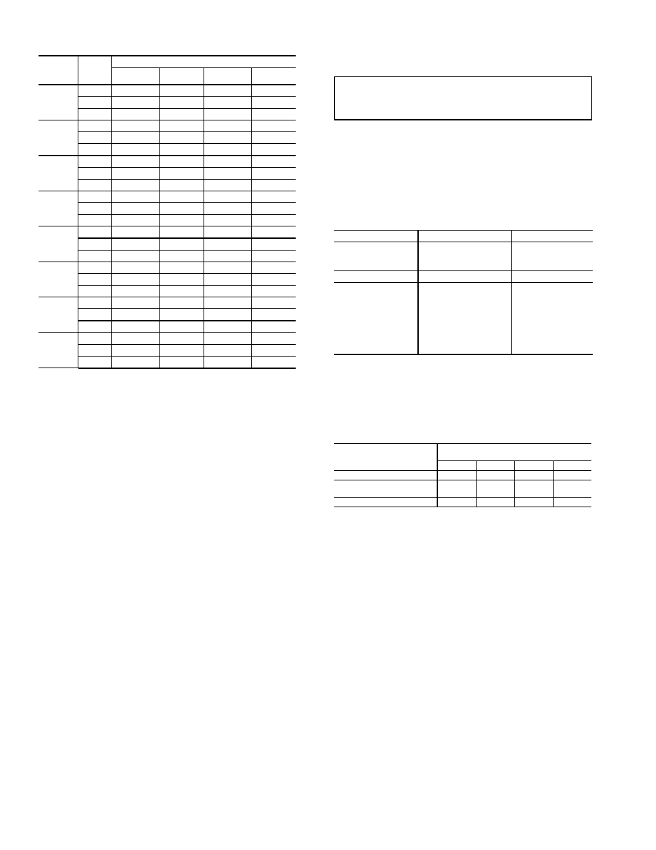
Table 17 — Coaxial Water Pressure Drop
NOTE: If air is purged from the system while using a
250 mm PVC flush tank, only a 25 to 50 mm level drop will
be noticed since liquids are incompressible. If the level
drops more than this, flushing should continue since air is
still being compressed in the loop. If level is less than 25 to
50 mm, reverse the flow.
8. Repeat this procedure until all air is purged.
9. Restore power.
Antifreeze may be added before, during or after the
flushing process. However, depending on when it is added
in the process, it can be wasted. Refer to the Antifreeze sec-
tion for more detail.
Loop static pressure will fluctuate with the seasons. Pres-
sures will be higher in the winter months than during the
warmer months. This fluctuation is normal and should be
considered when charging the system initially. Run the unit
in either heating or cooling for several minutes to condition
the loop to a homogenous temperature.
When complete, perform a final flush and pressurize the
loop to a static pressure of 275 to 350 kPa for winter months
or 100 to 140 kPa for summer months.
After pressurization, be sure to remove the plug from the
end of the loop pump motor(s) to allow trapped air to be
discharged and to ensure the motor housing has been flood-
ed. Be sure the loop flow center provides adequate flow
through the unit by checking pressure drop across the heat
exchanger.
Antifreeze —
In areas where entering loop temperatures
drop below 4.4 C or where piping will be routed through ar-
eas subject to freezing, antifreeze is needed.
Alcohols and glycols are commonly used as antifreeze
agents. Freeze protection should be maintained to 8.3° C below
the lowest expected entering loop temperature. For example, if
the lowest expected entering loop temperature is –1.1 C, the
leaving loop temperature would be –5.6 to –3.9 C. Therefore,
the freeze protection should be at –9.4 C (–1.1 C – 8.3 C =
–9.4 C) Calculate the total volume of fluid in the piping sys-
tem. See Table 18. Use the percentage by volume in
Table 19 to determine the amount of antifreeze to use. Anti-
freeze concentration should be checked from a well mixed
sample using a hydrometer to measure specific gravity. .
FREEZE PROTECTION SELECTION — The –1.1 C FP1
factory setting (water) should be used to avoid freeze damage
to the unit.
Once antifreeze is selected, the JW3 jumper (FP1) should
be clipped on the control to select the low temperature
(antifreeze –12.2 C) set point to avoid nuisance faults.
Table 18 — Approximate Fluid Volume (L)
per 30 M of Pipe
LEGEND
NOTE: Volume of heat exchanger is approximately 3.78 liters.
Table 19 — Antifreeze Percentages by Volume
Cooling Tower/Boiler Systems —
These systems
typically use a common loop maintained at 15.6 C to 32.2 C.
The use of a closed circuit evaporative cooling tower with a
secondary heat exchanger between the tower and the water
loop is recommended. If an open type cooling tower is
used continuously, chemical treatment and filtering will be
necessary.
Ground Coupled, Closed Loop and Plateframe
Heat Exchanger Well Systems —
These systems
allow water temperatures from –1.1 to 43.3 C. The external
loop field is divided up into 51 mm polyethylene supply and
return lines. Each line has valves connected in such a way
that upon system start-up, each line can be isolated for flush-
ing using only the system pumps. Air separation should be
located in the piping system prior to the fluid re-entering the
loop field.
OPERATION
Power Up Mode —
The unit will not operate until all
the inputs, terminals and safety controls are checked for
normal operation.
NOTE: The compressor will have a 5-minute anti-short
cycle upon power up.
50VQP
UNIT
SIZE
L/s
PRESSURE DROP (kPa)
–1 C
10 C
21 C
32 C
084
0.66
16.5
13.8
8.3
7.6
1.00
37.9
31.7
23.4
20.7
1.32
63.4
54.4
42.7
39.3
096
0.76
26.2
21.4
15.8
13.8
1.13
55.1
46.9
36.5
33.1
1.51
89.6
77.2
63.4
59.3
120
0.95
14.5
11.7
8.3
6.9
1.42
36.5
30.3
24.1
22.1
1.89
64.8
55.8
46.2
42.7
150
1.20
18.6
14.5
10.3
9.0
1.76
42.7
35.8
28.2
25.5
2.39
75.8
65.5
53.1
49.6
168
1.32
18.6
15.2
9.6
8.3
1.98
42.0
35.8
26.2
23.4
2.65
71.7
61.3
47.5
44.1
192
1.51
28.9
24.1
17.9
15.8
2.27
62.0
52.4
41.3
37.9
1.89
100.6
86.8
71.0
66.1
240
2.84
16.5
13.1
9.0
7.6
3.78
40.7
33.8
26.9
24.8
2.39
72.3
63.4
51.7
48.2
300
3.53
21.4
16.5
11.7
10.3
4.79
48.2
40.7
31.7
28.9
3.78
85.4
73.7
59.9
55.8
IMPORTANT: All alcohols should be pre-mixed and
pumped from a reservoir outside of the building or intro-
duced under water level to prevent alcohols from fuming.
PIPE
DIAMETER (in.) [mm] VOLUME (gal.) [L]
Copper
1 [25.4]
4.1 [15.5]
1.25 [31.8]
6.4 [24.2]
1.5 [38.1]
9.2 [34.8]
Rubber Hose
1 [25.4]
3.9 [14.8]
Polyethylene
3
/
4
IPS SDR11
2.8 [10.6]
1 IPS SDR11
4.5 [17.0]
1
1
/
4
IPS SDR11
8.0 [30.8]
1
/
2
IPS SDR11
10.9 [41.3]
2 IPS SDR11
18.0 [68.1]
1
1
/
4
IPS SCH40
8.3 [31.4]
1
1
/
2
IPS SCH40
10.9 [41.3]
2 IPS SCH40
17.0 [64.4]
IPS
— Internal Pipe Size
SCH — Schedule
SDR — Standard Dimensional Ratio
ANTIFREEZE
MINIMUM TEMPERATURE FOR FREEZE
PROTECTION (C)
–12.2
–9.4
–6.7
–3.9
Methanol (%)
25
21
16
10
100% USP Food Grade
Propylene Glycol (%)
38
30
22
15
Ethanol (%)
29
25
20
14