12 table 2 — water quality guidelines, Fig. 26 — typical ground-water piping installation – Carrier AQUAZONE 50VQP084-300 User Manual
Page 12
12
Table 2 — Water Quality Guidelines
LEGEND
*Heat exchanger materials considered are copper, cupronickel, 304 SS (stain-
less steel), 316 SS, titanium.
†Closed recirculating system is identified by a closed pressurized piping system.
**Recirculating open wells should observe the open recirculating design
considerations.
††If the concentration of these corrosives exceeds the maximum allowable level,
then the potential for serious corrosion problems exists.
Sulfides in the water quickly oxidize when exposed to air, requiring that no agi-
tation occur as the sample is taken. Unless tested immediately at the site, the
sample will require stabilization with a few drops of one Molar zinc acetate
solution, allowing accurate sulfide determination up to 24 hours after sam-
pling. A low pH and high alkalinity cause system problems, even when both
values are within ranges shown. The term pH refers to the acidity, basicity, or
neutrality of the water supply. Below 7.0, the water is considered to be acidic.
Above 7.0, water is considered to be basic. Neutral water contains a pH of 7.0.
NOTE: To convert ppm to grains per gallon, divide by 17. Hardness in mg/l is
equivalent to ppm.
CONDITION
HX
MATERIAL*
CLOSED RECIRCULATING†
OPEN LOOP AND RECIRCULATING WELL**
Scaling Potential — Primary Measurement
Above the given limits, scaling is likely to occur. Scaling indexes should be calculated using the limits below.
pH/Calcium Hardness Method
All
N/A
pH < 7.5 and Ca Hardness, <100 ppm
Index Limits for Probable Scaling Situations (Operation outside these limits is not recommended.)
Scaling indexes should be calculated at 150 F for direct use and HWG applications, and at 90 F for indirect HX use. A monitoring plan should be implemented.
Ryznar Stability Index
All
N/A
6.0 - 7.5
If >7.5 minimize steel pipe use.
Langelier Saturation Index
All
N/A
–0.5 to +0.5
If <–0.5 minimize steel pipe use.
Based upon 150 F HWG and direct well, 85 F indirect well HX.
Iron Fouling
Iron Fe
2+
(Ferrous)
(Bacterial Iron Potential)
All
N/A
<0.2 ppm (Ferrous)
If Fe
2+
(ferrous) >0.2 ppm with pH 6 - 8, O
2
<5 ppm check for iron bacteria.
Iron Fouling
All
N/A
<0.5 ppm of Oxygen
Above this level deposition will occur.
Corrosion Prevention††
pH
All
6 - 8.5
Monitor/treat as needed.
6 - 8.5
Minimize steel pipe below 7 and no open tanks with pH <8.
Hydrogen Sulfide (H
2
S)
All
N/A
<0.5 ppm
At H
2
S>0.2 ppm, avoid use of copper and cupronickel piping or HXs.
Rotten egg smell appears at 0.5 ppm level.
Copper alloy (bronze or brass) cast components are okay to <0.5 ppm.
Ammonia Ion as Hydroxide,
Chloride, Nitrate and Sulfate
Compounds
All
N/A
<0.5 ppm
Maximum Chloride Levels
Maximum allowable at maximum water temperature.
50 F (10 C)
75 F (24 C)
100 F (38 C)
Copper
N/A
<20 ppm
NR
NR
Cupronickel
N/A
<150 ppm
NR
NR
304 SS
N/A
<400 ppm
<250 ppm
<150 ppm
316 SS
N/A
<1000 ppm
<550 ppm
<375 ppm
Titanium
N/A
>1000 ppm
>550 ppm
>375 ppm
Erosion and Clogging
Particulate Size and Erosion
All
<10 ppm of particles and a
maximum velocity of 6 fps.
Filtered for maximum
800 micron size.
<10 ppm (<1 ppm “sandfree” for reinjection) of particles and a maximum velocity of
6 fps. Filtered for maximum 800 micron size. Any particulate that is not removed can
potentially clog components.
Brackish
All
N/A
Use cupronickel heat exchanger when concentrations of calcium or sodium chloride
are greater than 125 ppm are present. (Seawater is approximately 25,000 ppm.)
HWG — Hot Water Generator
HX
— Heat Exchanger
N/A
— Design Limits Not Applicable Considering Recirculating Potable Water
NR
— Application Not Recommended
SS
— Stainless Steel
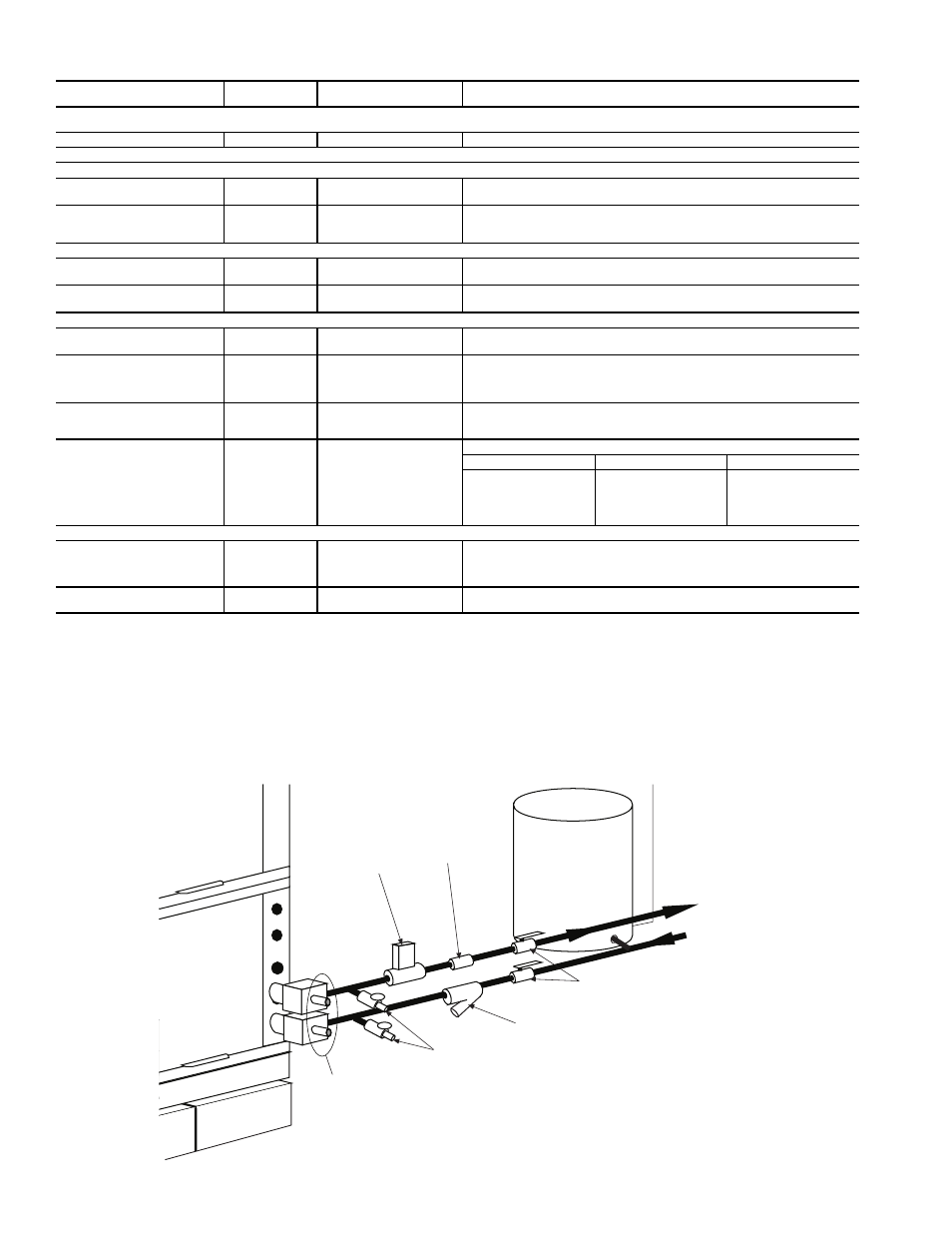
Pressure-
Temperature
Plugs
Boiler
Drains
Strainer – Field-Installed Accessory
(16 to 20 mesh recommended for
filter sediment)
Shut-Off
Valve
Water
Control
Valve
Automatic
Balance Valve
Expansion
Tank
Water Out
Water In
From Pump
Fig. 26 — Typical Ground-Water Piping Installation