Step 9 — field control wiring, Pre-start-up system checkout – Carrier AQUAZONE 50VQP084-300 User Manual
Page 17
17
Step 9 — Field Control Wiring
THERMOSTAT CONNECTIONS — The thermostat should
be wired directly to the Aquazone™ control board. See
Fig. 27-31.
WATER FREEZE PROTECTION — The Aquazone control
allows the field selection of source fluid freeze protection
points through jumpers. The factory setting of jumper JW3
(FP1) is set for water at –1.1 C. In earth loop applications,
jumper JW3 should be clipped to change the setting to –12.2 C
when using antifreeze in colder earth loop applications. See
Fig. 32.
AIR COIL FREEZE PROTECTION — The air coil freeze
protection jumper JW2 (FP2) is factory set for –1.1 C and
should not need adjusting.
ACCESSORY CONNECTIONS — Terminal labeled A on
the control is provided to control accessory devices such as
water valves, electronic air cleaners, humidifiers, etc. This
signal operates with the compressor terminal. See Fig. 33.
Refer to the specific unit wiring schematic for details.
NOTE: The A terminal should only be used with 24 volt
signals — not line voltage signals.
WATER SOLENOID VALVES — An external solenoid
valve(s) should be used on ground water installations to shut
off flow to the unit when the compressor is not operating. A
slow closing valve may be required to help reduce water
hammer. Figure 33 shows typical wiring for a 24-vac external
solenoid valve. Figures 34 and 35 illustrate typical slow closing
water control valve wiring for Taco 500 Series and Taco ESP
Series valves. Slow closing valves take approximately 60 sec.
to open (very little water will flow before 45 sec.). Once fully
open, an end switch allows the compressor to be energized (on-
ly on valves with end switches). Only relay or triac based elec-
tronic thermostats should be used with slow closing valves.
When wired as shown, the slow closing valve will operate
properly with the following notations:
1. The valve will remain open during a unit lockout.
2. The valve will draw approximately 25 to 35 VA through
the “Y” signal of the thermostat.
PRE-START-UP
System Checkout —
When the installation is complete,
follow the system checkout procedure outlined below before
starting up the system. Be sure:
1. Voltage is within the utilization range specifications of the
unit compressor and fan motor and voltage is balanced
for 3-phase units.
2. Fuses, breakers and wire are correct size.
3. Low voltage wiring is complete.
4. Piping and system flushing is complete.
5. Air is purged from closed loop system.
6. System is balanced as required. Monitor if necessary.
7. Isolation valves are open.
8. Water control valves or loop pumps are wired.
Fig. 31 — Low Voltage Field Wiring
COMPLETE C CONTROL
CAPACITOR
LINE
LO
AD
COMPRESSOR CONTACTOR
TRANSFORMER
Y
GGGG
R
W
O
Y2
Y1
G
R
C
Y2 Y1 G
O W C R DH AL1 A
A
AL1
SW1
SW2
SW3
SW4
SW5
SW6
SW7
SW8
SW9
OFF
ON
G DEHUM
CFM
TB1
J1
S1
THERMOSTAT CONNECTION
a50-8197
NOTE: Low voltage connector may be removed for
easy installation.
AQUAZONE CONTROL (Complete C Control Shown)
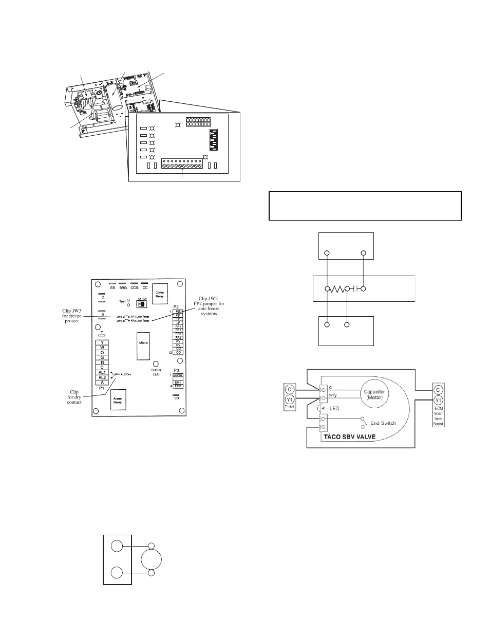
Fig. 32 — Typical Aquazone™ Control Board
Jumper Locations
a50-
6268tf.tif
TYPICAL
WATER
VALVE
C
A
24 VAC
TERMINAL STRIP P2
Fig. 33 — Typical Aquazone Accessory Wiring
(Control D Shown)
IMPORTANT: Connecting a water solenoid valve can
overheat the anticipators of electromechanical thermo-
stats. Only use relay based electronic thermostats.
Fig. 35 — Taco SBV Valve Wiring
Fig. 34 — AMV Valve Wiring
C
C
THERMOSTAT
1
Y
1
2
3
1
Y
AMV
TACO VALVE
HEATER SWITCH
a50-8441
a50-8442