EVCO EVK404N9 User Manual
Page 7
Evco S.p.A. • Code 104K404E114 • page 7/8
C1
0
240
min
0
0
0
0
0
0
0
0
0
0
C2
0
240
min
0
0
0
0
0
0
0
0
0
0
C3
0
240
s
0
0
0
0
0
0
0
0
0
0
C4
0
3
- - - -
0
0
0
0
0
0
0
0
0
0
C5
0
3
- - - -
not avail.not avail. not avail. not avail. not avail. not avail. not avail. not avail.
0
0
C11
0
240
s
5
5
5
5
5
5
5
5
5
5
C12
0
240
s
0
0
0
0
0
0
0
0
0
0
C13
0
6
- - - -
0
0
0
not avail.
0
0
0
0
not avail. not avail.
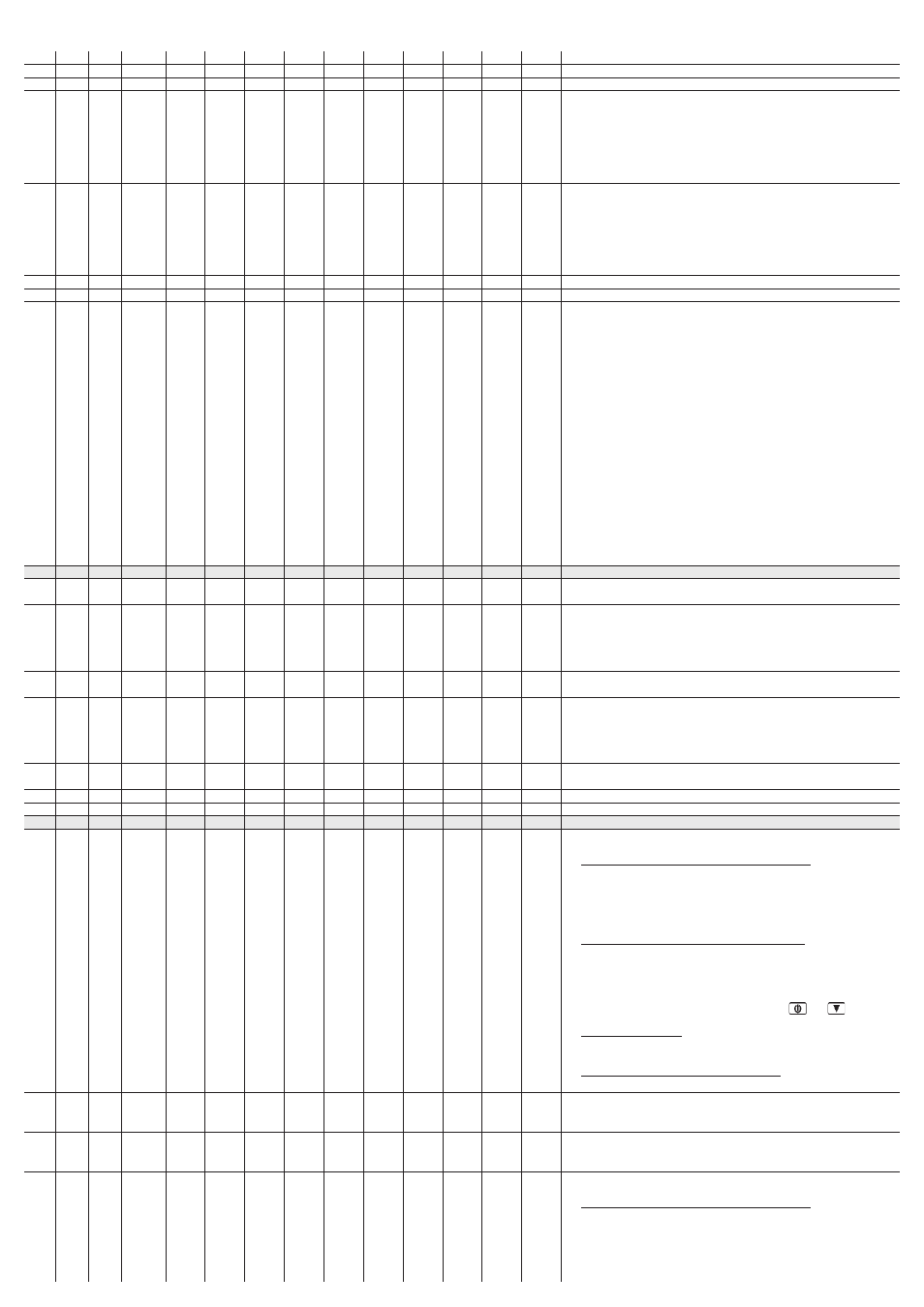
PAR.
MIN.
MAX. U. M.
CFG = 0 CFG = 1 CFG = 2 CFG = 3 CFG = 4 CFG = 5 CFG = 6 CFG = 7 CFG = 8 CFG = 9
A1
-199.0 9990
°C/°F (1)
-50.0
-50.0
-50.0
-50.0
-50.0
-50.0
-50.0
-50.0
-50.0
-50.0
A2
0
2
- - - -
2
2
2
2
2
2
2
2
2
2
A4
-199.0 9990
°C/°F (1)
150.0
150.0
150.0
150.0
150.0
150.0
150.0
150.0
150.0
150.0
A5
0
2
- - - -
2
2
2
2
2
2
2
2
2
2
A6
0
240
min
120
120
120
120
120
120
120
120
120
120
A7
0
240
min
15
15
15
15
15
15
15
15
15
15
A11
0.1
99.0
°C/°F (1)
2.0
2.0
2.0
2.0
2.0
2.0
2.0
2.0
2.0
2.0
PAR.
MIN.
MAX. U. M.
CFG = 0 CFG = 1 CFG = 2 CFG = 3 CFG = 4 CFG = 5 CFG = 6 CFG = 7 CFG = 8 CFG = 9
i0
0
4
- - - -
0
0
0
0
not avail. not avail. not avail.
0
0
0
i1
0
1
- - - -
0
0
0
0
0
0
0
0
0
0
i2
-1
120
min
120
120
120
120
120
120
120
120
120
120
i5
0
4
- - - -
0
0
0
0
0
0
0
0
0
0
minimum time between two consecutive switch-ons of the same relay (9)
minimum switch off time of the same relay (9)
minimum switch on time of the same relay
state of the relays used for regulation during probe 1 error (code “Pr1”)
0 = the relays will be off
1 = the relays will be switched on (10)
2 = the cooling mode operation relays will be on and the heating mode operation
relays will be off (10)
3 = the heating mode operation relays will be on and the cooling mode operation
relays will be off (10)
state of the relays used for regulation during probe 2 error (code “Pr2”)
0 = the relays will be off
1 = the relays will be switched on (10)
2 = the direct operation relays will be switched on and the inverse operation relays
will be switched off (10)
3 = the heating mode operation relays will be on and the cooling mode operation
relays will be off (10)
minimum time between two consecutive switch-ons of two different relays (9)
minimum time between two consecutive switch-offs of two different relays
type of relays switch-on and switch-off sequence
0 = fixed sequence (the relays will be on and off as indicated in the drawings in
chapter 4, Last In First Out)
1 = the first relay that will be switched on will be that off for the longest period of time
and the first to be switched off will be that on for the longest period of time (First
In First Out)
2 = this sequence has been studied for the management of split compressors with
valve activated with relay on. In this case the utilities managed by the relays must
be the following:
relay K1 = compressor 1
relay K2 = compressor 1 valve
relay K3 = compressor 2
relay K4 = compressor 2 valve
the switch-on sequence will be the same in the case C13 = 1 but relative to relays
1 and 3 (11)
3 = the same as the previous case but relevant to the valves activated with relay off (12)
4 = the same as case C13 = 1 but relative to relays 3 and 4
5 = the same as case C13 = 1 but relative to relays 1 and 2
6 = the same as case C13 =1 but relative to relays 1 and 2 (with each other) and to
relays 3 and 4 (with each other)
MINIMUM ALARM AND MAXIMUM ALARM (13)
magnitude value below which the minimum alarm is activated (code “AL”); see also
A2 and A11
minimum alarm type (code “AL”)
0 = no alarm
1 = relative to the work set-point (i.e.“work set-point SP1 - A1” or “work set-point SP2
- A1”; consider A1 without sign) (14)
2 = absolute (i.e. A1)
magnitude value above which the maximum alarm is activated (code “AH”); see also
A5 and A11
maximum alarm type (code “AH”)
0 = no alarm
1 = relative to the work set-point (i.e. “work set-point SP1 - A4” or “work set-point SP2
- A4”; consider A4 without sign) (15)
2 = absolute (i.e. A4)
minimum alarm delay (code “AL”) and maximum alarm (code “AH”) from device
switch-on (8)
minimum alarm delay (code “AL”) and maximum alarm (code “AH”)
parameters A1 and A4 differential
DIGITAL INPUTS
effect caused by the activation of digital input 1
0 = no effect
1 = ACTIVATION OF AUTOMATIC RESTORE EXTERNAL ALARM - on expiry of time i2
the relays used for regulation will be forced into the state established with
parameter C5.
Any relays for signalling alarms and errors (CFG = 3) will be on, the display will
show the “id1” code flashing and the buzzer will be activated. When the cause
f the alarm disappears, the device restores normal operation
2 = ACTIVATION OF MANUAL RESTORE EXTERNAL ALARM - on expiry of time i2
the relays used for regulation will be forced into the state established with
parameter C5.
Any relays for signalling alarms and errors (CFG = 3) will be on, the display will
show the “iSd1” code flashing and the buzzer will be activated.
The cause of the alarm must disappear and then the
and
keys must be
pressed for 1 s in order for the device to restore normal operation
3 = DEVICE SWITCH-ON/OFF - on expiry of time C3, the device will be off (stand-by
state) and the display will show the magnitude established with parameter P5 for
½ s every 4 s (while the input remains active)
4 = ACTIVATION OF THE WORK PROGRAM FUNCTION - if r23 = 2, the Work Program
function is activated (see paragraph 4.5)
type of digital input 1 contact
0 = normally open (input active with closed contact)
1 = normally closed (input active with open contact)
external alarm delay from digital input 1 (codes “id1” and “iSd1”) and external alarm
from digital input 2 (codes “id2” and “iSd2”)
-1= the alarm will not be signalled
effect caused by the activation of digital input 2
0 = no effect
1 = ACTIVATION OF AUTOMATIC RESTORE EXTERNAL ALARM - on expiry of time i2
the relays used for regulation will be forced into the state established with
parameter C5.
Any relays for signalling alarms and errors (CFG = 3) will be on, the display will
show the “id2” code flashing and the buzzer will be activated. When the cause
f the alarm disappears, the device restores normal operation