EVCO EVK404N9 User Manual
Page 3
Evco S.p.A. • Code 104K404E114 • page 3/8
Operation with summer compensation of the work set-point SP1 (pa-
rameter P9 = 2); only is CFG = 0, 1, 2 or 3
Example 1: parameter r16 is set at a positive value.
Example 2: parameter r16 is set at a negative value.
CODE MEANING
SP1
work set-point SP1
r16
maximum value of the summer compensation of the work
set-point SP1
r17
value of the magnitude detected by probe 2 over
which summer compensation of the work set-point SP1
is started
r18
value of the magnitude detected by probe 2 over
which summer compensation of the work set-point SP1
is concluded
The value of the work set-point SP 1 is however subject to the values
established with parameters r1 and r2.
Operation with winter compensation of the work set-point SP1
(parameter P9 = 3); only is CFG = 0, 1, 2 or 3
Example 1: parameter r16 is set at a positive value.
Example 2: parameter r16 is set at a negative value.
CODE MEANING
SP1
work set-point SP1
r16
maximum value of the winter compensation of the work
set-point SP1
r19
value of the magnitude detected by probe 2 below
which summer compensation of the work set-point SP1
is concluded
r20
value of the magnitude detected by probe 2 below
which winter compensation of the work set-point SP1
is started
The value of the work set-point SP 1 is however subject to the values
established with parameters r1 and r2.
Operation with combined compensation of the work set-point SP1
(parameter P9 = 4); only is CFG = 0, 1, 2 or 3
Example 1: parameter r16 is set at a positive value.
Example 2: parameter r16 is set at a negative value.
CODE MEANING
SP1
work set-point SP1
SP2
work set-point SP2
r6
neutral area value with combined compensation opera-
tion of the work set-point SP1
r18
value of the magnitude detected by probe 2 over which
combined compensation of the work set-point SP1 is
concluded (relative to “SP2 + r6”)
r19
value of the magnitude detected by probe 2 below which
combined compensation of the work set-point SP1 is
concluded (relative to “SP2 - r6”)
The value of the work set-point SP 1 is however subject to the values
established with parameters r1 and r2.
4.5
Work program function
The Work Program function allows to reach and maintain five
magnitudes (with different values) during five respective time intervals
(hereon called phases).
On conclusion of a phase, the device passes automatically to the next
one; on conclusion of the fifth phase the device restores normal op-
eration and the function is concluded.
If the magnitude has not reached the respective value at the conclu-
sion of a phase, the device will still pass to the next phase.
If the duration of the first ... fourth phase is set at a nil value, on reaching
the respective value, the device will pass to the next phase. If the dura-
tion of the fifth phase is set at a nil value, the phase will continue until
the function is interrupted in manual mode.
If a power cut occurs during operation, this will be concluded.
To activate/deactivate the function:
The activation/deactivation mode of the function depends on
parameter r23:
• if parameter r23 is set at 0, the function will be absent
• if parameter r2 is set at 1, the
key must be pressed for 4 s, on
condition that the keyboard is not blocked
• if parameter r23 is set at 2, it will be necessary to activate the digital
input 1 (or digital input 2), on condition that the parameter i0 (or the
parameter i5) is set at 4.
When the function is interrupted, the display will show the “StOP”
indication flashing for 4 s.
During the function:
During the function, the display shows the “Ph” indication followed
by the number of the phase (for example “Ph2”) for ½ s every 4 s.
On conclusion of the function:
On conclusion of the function, the display shows the “EndP”
indication flashing ½ s every 4 s; press a key to delete the “EndP”
indication.
CODE MEANING
r24
duration of the first phase of the work program
r25
magnitude detected by probe 1 to be reached and
maintained during the first phase of the work program
r27
duration of the second phase of the work program
r28
magnitude detected by probe 1 to be reached and main-
tained during the second phase of the work program
r30
duration of the third phase of the work program
r31
magnitude detected by probe 1 to be reached and
maintained during the third phase of the work program
r33
duration of the fourth phase of the work program
r34
magnitude detected by probe 1 to be reached and
maintained during the fourth phase of the work program
r36
duration of the fifth phase of the work program
r37
magnitude detected by probe 1 to be reached and
maintained during the fifth phase of the work program
If CFG parameter is set at 8, the function will allow to reach and
maintain five magnitudes detected by probe 1 and five magnitudes
detected by probe 2.
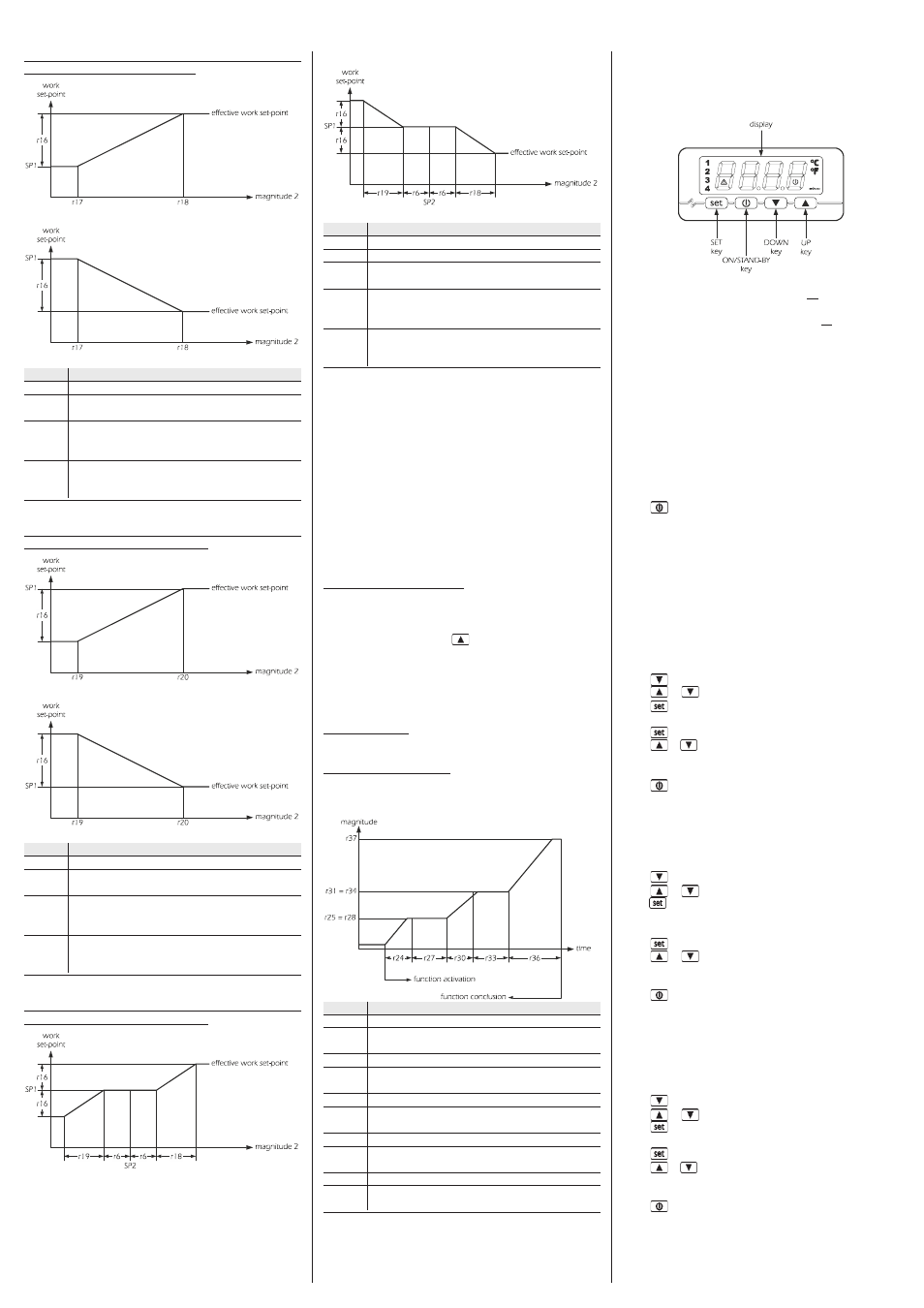
5
USER INTERFACE
5.1
Foreword
The user interface is composed of a custom 4 digit display (with deci-
mal point and function icons) and by 4 keys (SET, UP, DOWN and
ON/STAND-BY).
The following operating states exist:
• “on” state (the device is powered and is on: the relays can be
switched on)
• the “stand-by” state (the device is powered but is off via software: the
relays are off)
• the “off” state (the device is not powered).
Hereon, the term "switch on" means the passage from the stand-by
state to the on state. The term "switch off" means passage from the on
state to the stand-by state.
When powered, the device will be in the same state as when the power
supply was cut-off.
5.2
Device switch-on/off in manual mode
• make sure that the keyboard is not blocked and that no procedure
is in progress
• make sure that the device has not switched off in remote mode (pa-
rameter i0 = 3 and digital input 1 active and/or parameter i5 = 3 and
digital input 2 active)
• press
for 1 s: the on/stand-by LED will switch off/on.
Using the digital inputs 1 and 2 it is also possible to switch the device
on/off in remote mode.
5.3
The display
If the device is on, during normal operation the display will show the
magnitude established with parameter P5:
• if P5 = 0, the display will show the magnitude detected by probe 1
• if P5 = 1, the display will show the magnitude detected by probe 2.
If the device is off (stand-by state), the display will be off.
5.4
Display of the magnitude detected by probe 1
and the magnitude detected by probe 2
• make sure that the keyboard is not blocked and that no procedure
is in progress
• press
for 1 s: the display will show the first label available
• press
or
to select “Pb1” or “Pb2”
• press
To exit the procedure:
• press
or do not operate for 60 s
• press
or
until the display shows the magnitude established
with parameter P5 or do not operate for 60 s.
Alternatively:
• press
If probe 2 is absent (parameter P9 = 0 or parameter CFG = 4, 5, 6 or
7), the “Pb2” label will not be displayed.
5.5
Display of the state of the digital input 1 and
the state of the digital input 2
• make sure that the keyboard is not blocked and that no procedure
is in progress
• press
for 1 s: the display will show the first label available
• press
or
to select “id1” or “id2”
• press
: the display will show “on” (active input) or “oFF”
(non-active input).
To exit the procedure:
• press
or do not operate for 60 s
• press
or
until the display shows the magnitude established
with parameter P5 or do not operate for 60 s.
Alternatively:
• press
If the activation of the digital input 1 does not have any effect
(parameter i0 = 0), the “id1” label will not be displayed.
If the activation of the digital input 2 does not have any effect
(parameter i5 = 0), the “id2” label will not be displayed.
5.6
Learning the type of operation in progress
• make sure that the keyboard is not blocked and that no procedure
is in progress
• press
for 1 s: the display will show the first label available
• press
or
to select “CFG”
• press
To exit the procedure:
• press
or do not operate for 60 s
• press
or
until the display shows the magnitude established
with parameter P5 or do not operate for 60 s.
Alternatively:
• press