Vga port – Digilent Basys Board Rev.C User Manual
Page 8
Digilent
Basys Reference Manual
www.digilentinc.com
Copyright Digilent, Inc.
Page 8/12
Doc: 502-107
bits 0, 11, and 22 are ‘0’ start bits, and bits 11, 21, and 33 are ‘1’ stop bits. The three 8-bit data fields
contain movement data as shown below. Data is valid at the falling edge of the clock, and the clock
period is 20 to 30KHz.
The mouse assumes a relative coordinate system wherein moving the mouse to the right generates a
positive number in the X field, and moving to the left generates a negative number. Likewise, moving
the mouse up generates a positive number in the Y field, and moving down represents a negative
number (the XS and YS bits in the status byte are the sign bits – a ‘1’ indicates a negative number).
The magnitude of the X and Y numbers represent the rate of mouse movement – the larger the
number, the faster the mouse is moving (the XV and YV bits in the status byte are movement overflow
indicators – a ‘1’ means overflow has occurred). If the mouse moves continuously, the 33-bit
transmissions are repeated every 50ms or so. The L and R fields in the status byte indicate Left and
Right button presses (a ‘1’ indicates the button is being pressed).
VGA Port
L
R
0
1 XS YS XY YY P
X0 X1 X2 X3 X4 X5 X6 X7 P
Y0 Y1 Y2 Y3 Y4 Y5 Y6 Y7 P
1
0
1
0
0
1
1
Idle state
Start bit
Stop bit
Start bit
Mouse status byte
X direction byte
Y direction byte
Stop bit
Start bit
Stop bit
Idle state
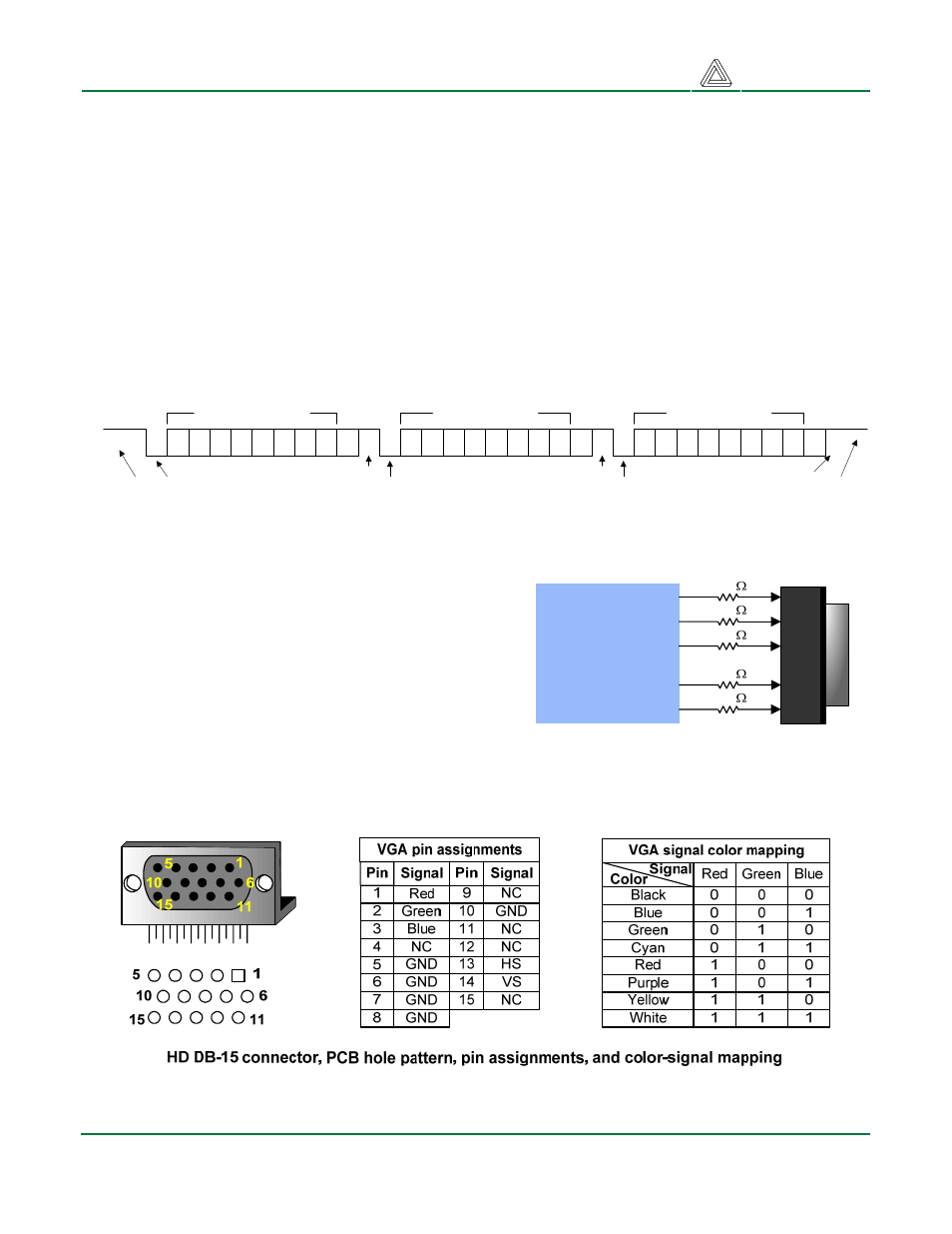
The five standard VGA signals Red, Green, Blue,
Horizontal Sync (HS), and Vertical Sync (VS) are
routed directly from the FPGA to the VGA connector,
resulting in a simple video system that can produce
eight colors. The color signals from the FPGA include
270-ohm series resistors that form a divider with the
75-ohm termination resistance of the VGA display.
This simple circuit ensures that the video signals
cannot exceed the VGA-specified maximum voltage,
and results in color signals that are either fully on
(.7V) or fully off (0V).
49
Spartan 3E
FPGA
RED
GRN
BLU
HS
VS
47
48
41
40
270
270
270
200
200
Basys VGA Circuit Diagram
VGA signal timings are specified, published, copyrighted and sold by the VESA organization
(www.vesa.org). The following VGA system timing information is provided as an example of how a