Digilent Basys Board Rev.C User Manual
Page 6
Digilent
Basys Reference Manual
www.digilentinc.com
Copyright Digilent, Inc.
Page 6/12
Doc: 502-107
display will show “17” in the first two digits. An example timing diagram for a four-digit controller is
provided.
Ports and External Connectors
PS/2 Port
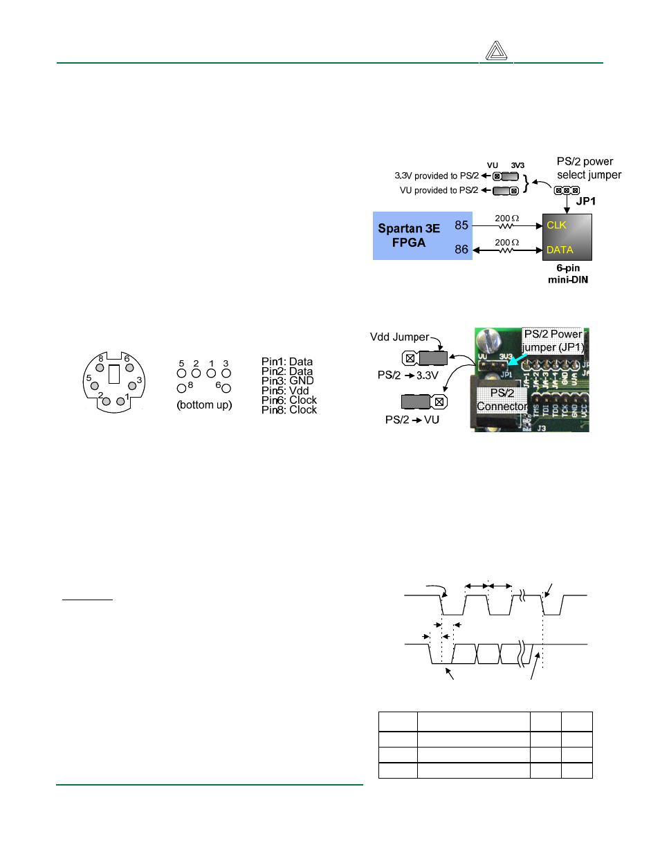
The Basys board includes a 6-pin mini-DIN connector
that can accommodate a PS/2 mouse or keyboard
connection. Most PS/2 devices can operate from a
3.3V supply, but some devices, like older keyboards,
require a 5VDC supply. A jumper on the Basys board
(JP1) can be used to select whether 3.3V or VU is
supplied to the PS/2 Vdd pin. If 5V is required, set JP1
to VU and ensure that Basys is powered with a 5VDC
wall-plug supply (note that Basys ships with a 5VDC
wall-plug supply).
PS/2 connector pin locations, pin assignments, and jumper settings
Both the mouse and keyboard use a two-wire serial bus (clock and data) to communicate with a host
device. Both use 11-bit words that include a start, stop and odd parity bit, but the data packets are
organized differently, and the keyboard interface allows bi-directional data transfers (so the host
device can illuminate state LEDs on the keyboard). Bus timings are shown in the figure. The clock and
data signals are only driven when data transfers occur, and otherwise they are held in the “idle” state
at logic ‘1’. The timings define signal requirements for mouse-to-host communications and bi-
directional keyboard communications.
T
CK
T
SU
Edge 0
Edge 10
CLK
DATA
T
HLD
T
CK
'1' stop bit
'0' start bit
Keyboard
The keyboard uses open-collector drivers so that either
the keyboard or an attached host device can drive the
two-wire bus (if the host device will not send data to the
keyboard, then the host can use input-only ports).
PS2-style keyboards use scan codes to communicate
key press data (nearly all keyboards in use today are
PS2 style). Each key has a single, unique scan code
that is sent whenever the corresponding key is
pressed. If the key is pressed and held, the scan code
will be sent repeatedly about once every 100ms. When
a key is released, a “F0” key-up code is sent, followed
T
CK
T
SU
Clock time
Data-to-clock setup time
30us
5us
50us
Symbol
Parameter
Min
Max
25us
T
HLD
Clock-to-data hold time
5us
25us