Digilent Basys Board Rev.C User Manual
Page 5
Digilent
Basys Reference Manual
www.digilentinc.com
Copyright Digilent, Inc.
Page 5/12
Doc: 502-107
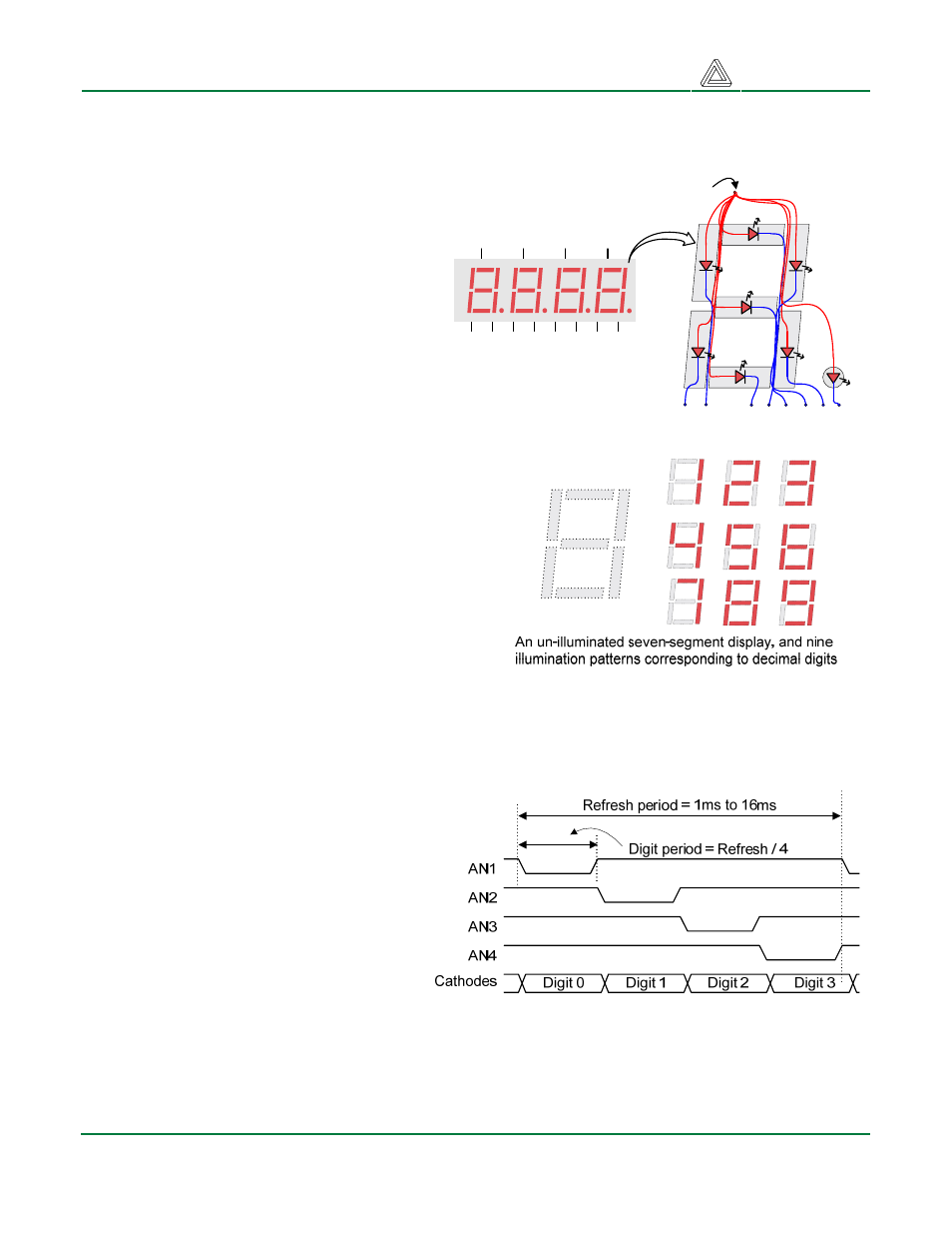
displayed on a digit by illuminating certain LED segments and leaving the others dark. Of these 128
possible patterns, the ten corresponding to the decimal digits are the most useful.
The anodes of the seven LEDs forming
each digit are tied together into one
“common anode” circuit node, but the LED
cathodes remain separate. The common
anode signals are available as four “digit
enable” input signals to the 4-digit display.
The cathodes of similar segments on all four
displays are connected into seven circuit
nodes labeled CA through CG (so, for
example, the four “D” cathodes from the
four digits are grouped together into a single
circuit node called “CD”). These seven
cathode signals are available as inputs to
the 4-digit display. This signal connection
scheme creates a multiplexed display, where the
cathode signals are common to all digits but they
can only illuminate the segments of the digit whose
corresponding anode signal is asserted.
A
F
E
D
C
B
G
Common anode
Individual cathodes
DP
AN1
AN2
AN3
AN4
CA CB CC CD CE CF CG DP
Four-digit Seven
Segment Display
A scanning display controller circuit can be used to
show a four-digit number on this display. This
circuit drives the anode signals and corresponding
cathode patterns of each digit in a repeating,
continuous succession, at an update rate that is
faster than the human eye can respond. Each digit
is illuminated just one-quarter of the time, but
because the eye cannot perceive the darkening of
a digit before it is illuminated again, the digit appears continuously illuminated. If the update or
“refresh” rate is slowed to a given point (around 45 hertz), then most people will begin to see the
display flicker.
In order for each of the four digits to
appear bright and continuously
illuminated, all four digits should be driven
once every 1 to 16ms (for a refresh
frequency of 1KHz to 60Hz). For example,
in a 60Hz refresh scheme, the entire
display would be refreshed once every
16ms, and each digit would be illuminated
for ¼ of the refresh cycle, or 4ms. The
controller must assure that the correct
cathode pattern is present when the
corresponding anode signal is driven. To
illustrate the process, if AN1 is asserted
while CB and CC are asserted, then a “1” will be displayed in digit position 1. Then, if AN2 is asserted
while CA, CB and CC are asserted, then a “7” will be displayed in digit position 2. If A1 and CB, CC
are driven for 4ms, and then A2 and CA, CB, CC are driven for 4ms in an endless succession, the