Digilent Basys Board Rev.C User Manual
Page 4
Digilent
Basys Reference Manual
www.digilentinc.com
Copyright Digilent, Inc.
Page 4/12
Doc: 502-107
3.3V
Slide
switches
Spartan 3E
FPGA
13
30
69
94
92
91
90
89
11
88
BTN0
BTN1
BTN2
BTN3
SW0
SW1
SW2
SW3
SW4
SW5
SW6
SW7
3.3V
LD0
LD1
LD2
LD3
LD4
LD5
LD6
LD7
3.3V
LEDs
Sseg
Display
AN1
AN2
AN3
AN4
95
98
15
12
10
9
5
4
3
2
33
32
27
26
42
24
22
17
16
43
23
CA
CB
CC
CD
CE
CF
CG
DP
18
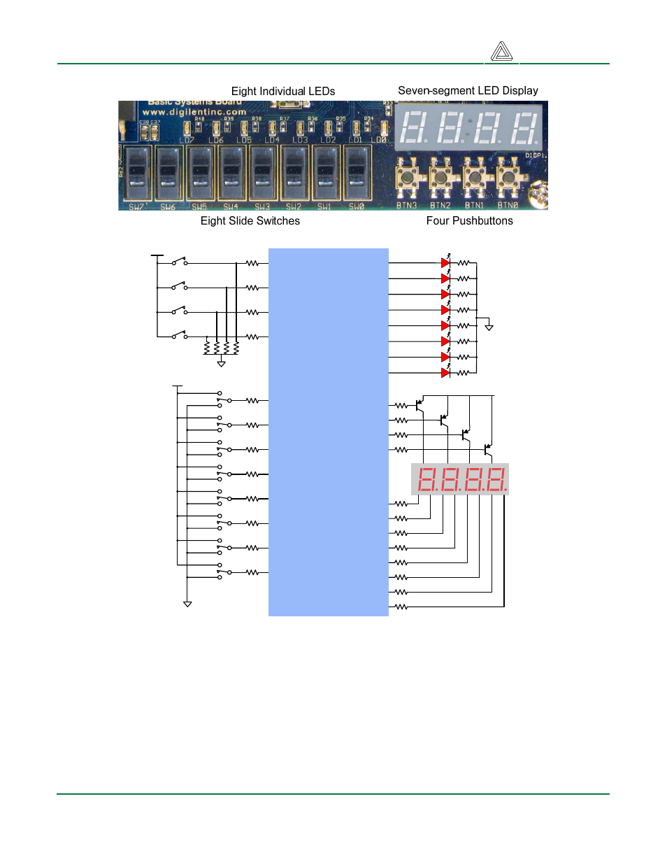
Outputs: LEDs
Eight LEDs are provided for circuit outputs. LED anodes are driven from the FPGA via 390-ohm
resistors, so a logic ‘1’ output will illuminate them with 3-4ma of drive current. A ninth LED is provided
as a power-on LED, and a tenth LED indicates FPGA programming status.
Outputs: Seven-Segment Display
The Basys board contains a four-digit common anode seven-segment LED display. Each of the four
digits is composed of seven segments arranged in a “figure 8” pattern, with an LED embedded in
each segment. Segment LEDs can be individually illuminated, so any one of 128 patterns can be
- 410-282P-KIT (4 pages)
- 410-279P-KIT (26 pages)
- 410-258P-KIT (16 pages)
- 410-138P-KIT (28 pages)
- 410-178P-KIT (22 pages)
- 410-292P-KIT (29 pages)
- 410-274P-KIT (29 pages)
- 410-182P-KIT (22 pages)
- 410-134P-KIT (17 pages)
- 410-183P-KIT (19 pages)
- 410-155P-KIT (12 pages)
- 6015-410-001P-KIT (26 pages)
- 410-087P-KIT (164 pages)
- 410-146P-KIT (4 pages)
- 6003-410-000P-KIT (138 pages)
- XUPV2P (23 pages)
- 410-047-C2P-KIT (3 pages)
- WaveForms (85 pages)
- 410-297P-KIT (25 pages)
- 410-295P-KIT (37 pages)
- 410-296P-KIT (23 pages)
- 410-209P-KIT REV.D (16 pages)
- 410-209P-KIT REV.C (17 pages)
- 410-254P-KIT (17 pages)
- 410-280P-KIT (9 pages)
- 410-202P-KIT (20 pages)
- 410-273P-KIT (24 pages)
- 410-269P-KIT (11 pages)
- 410-216P-KIT (15 pages)
- 410-231P-KIT (4 pages)
- 410-211P-KIT (10 pages)
- 410-262P-KIT (8 pages)
- 410-229P (7 pages)
- 410-242P-KIT (4 pages)
- 6021-210-000P-KIT (27 pages)
- 410-185P-KIT (21 pages)
- 6032-410-000P-BOARD (4 pages)
- 410-174P (17 pages)
- 410-145P (6 pages)
- 210-264P-BOARD (3 pages)
- 6003-210-012P (27 pages)
- 410-236P-BOARD (2 pages)
- 410-163P (1 page)
- 410-097P-KIT (2 pages)
- 410-255P-KIT (1 page)