Digilent Basys Board Rev.C User Manual
Page 12
Digilent
Basys Reference Manual
www.digilentinc.com
Copyright Digilent, Inc.
Page 12/12
Doc: 502-107
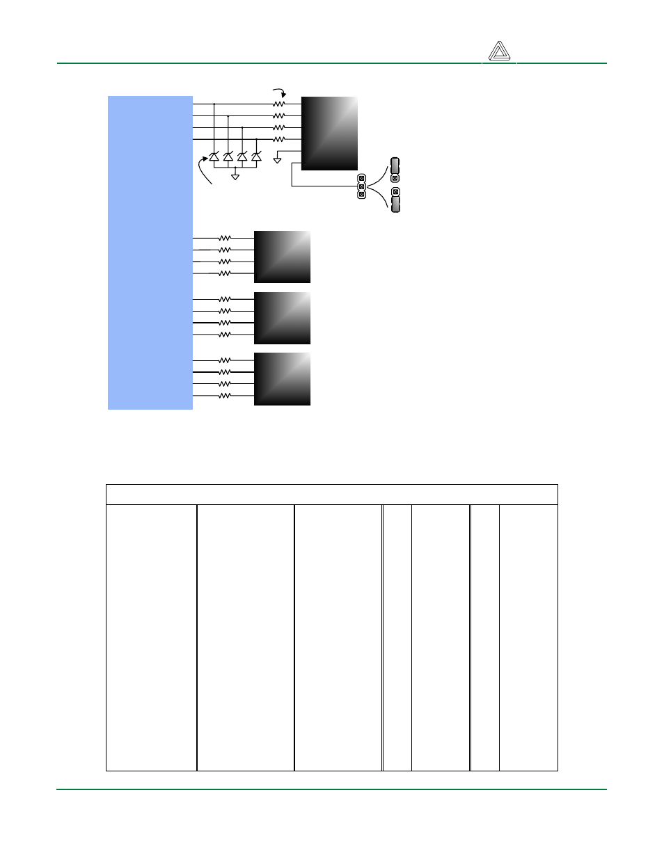
Spartan 3E
FPGA
79
78
71
70
ESD protection
diodes
1
6-pin
header
2
3
4
5
6
JA
Resistors for short-
circuit protection
Power
supply
jumper
VU
3.3V
JPA
1
6-pin
header
2
3
4
JB
1
6-pin
header
2
3
4
JC
1
6-pin
header
2
3
4
JD
68
67
66
65
63
62
61
60
58
57
54
53
FPGA
The pinout for the Spartan 3E-100 FPGA in the VQ100 package is shown in the table below.
Basys FPGA Pin Assignments
Pin
Function Pin
Function Pin
Function Pin Function Pin
Function
1
PROG_B
21
V
AUX
41 VGA-HS
61 JC-3
81
GND
2 LD7
22 CC
42 MODE1/C
62 JC-2
82
3V3
3
LD6
23 CG
43 MODE0/C
63 JC-1
83 SPI-SS
4 LD5
24 CB
44
D0
64
GND
84 CLK2
5 LD4
25
3V3
45
3V3
65 JB-4
85 PS2C
6
V
INT
26 AN4
46
V
AUX
66 JB-3
86 PS2D
7
GND
27 AN3
47 VGA-G
67 JB-2
87
GND
8
3V3
28
V
INT
48 VGA-B
68 JB-1
88 SW7
9 LD3
29
GND
49 VGA-R
69 BTN0
89 SW6
10 LD2
30 BTN1
50
CCLK
70 JA-4
90 SW5
11 BTN3
31
3V3
51
V
AUX
71 JA-3
91 SW4
12 LD1
32 AN2
52
GND
72
GND
92 SW3
13 BTN2
33 AN1
53 JD-4
73
3V3
93
GND
14
GND
34 SPI-MOSI
54 JD-3
74
V
AUX
94 SW2
15 LD0
35 SPI-MISO
55
3V3
75
TMS
95 SW1
16 CE
36 CLK1
56
V
INT
76
TDO
96
V
AUX
17 CD
37
GND
57 JD-2
77
TCK
97
3V3
18 DP
38 SPI-SCK
58 JD-1
78 JA2
98 SW0
19
GND
39
MODE2
59
GND
79 JA1
99
TMS-EN
20
3V3
40 VGA-VS
60 JC-4
80
V
INT
100
TDI
6-pin header connector circuit diagram. ESD diodes
and power jumper shown for JA are present for the
other connectors but omitted from the drawing.