Connecting the power – Comtrol IOLM 4-EIP User Manual
Page 10
10 -
Chapter 2. Hardware Installation
IO-Link Master 4-EIP User Guide: 2000582 Rev. A
Connecting the Power
2.4. Connecting the Power
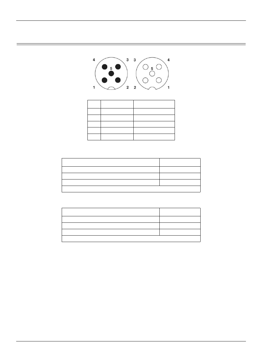
The IO-Link Master provides dual M12 (A-coded) power connectors.
Maximum EMC protection is provided by a low impedance connection between functional earth, the
grounding tabs, and protective earth. The following table contains power-related information about the power
supply.
Note: IO-Link Master requires a UL listed power supply with an output rating of 24VDC.
You can use this procedure to connect the IO-Link Master to a power supply.
1.
Securely attach the power cable between the male power connector and the power supply.
2.
Either attach a power cable between the female power connector and another device to which you want to
provide power or securely attach a connector cap to prevent dust or liquids from getting into the
connector. Connector caps were shipped with the IO-Link Master.
3.
Apply the power and verify that the following LEDs are lit indicating that you are ready to begin
configuration.
•
PWR
•
MS, first the flashing green and red LEDs displays that it is in self-test mode. After the self-test,
depending on whether you set the IP address with the rotary switch one of the following occurs:
-
The green LED is flashing to indicate that it is in standby mode.
-
The green LED is lit to indicate that it is operational.
•
NET, first it flashes green and red indicating that it is in self-test mode. After the self-test, depending
on whether you set the IP address with the rotary switch one of the following occurs:
-
Off indicates there is no IP address
Pin
Input - Male Output - Female
1
L+
L+
2
L2+
L2+
3
L-
L-
4
L2-
L2-
5
Not connected Not connected
Power Supply Voltage/Current
Values
Voltage Input Range
20 to 30VDC
Current (for the IO-Link Master)
100mA
Maximum Output Current
1.9A
†
† The total supply of current for all connected IO-Link devices.
Power Supply Voltage/Current
Values
Voltage Input Range
Current (for the IO-Link Master)
Maximum Output Current
† The total supply of current for all connected IO-Link devices.