Toshiba IK-DP20A User Manual
Page 33
Attention! The text in this document has been recognized automatically. To view the original document, you can use the "Original mode".
Camera Address = 1 x bit1 Status + 2 x bit2 Status + 4 x bits Status + 8 x bit4
Status + 16
X
bits Status + 32 x bit6 Status + 64 x bit7
Status + 128
X
bit8 Status
*bit Status: On=1 ,Off=0
ex) Camera Address 200 =1 x O(Off) + 2 x O(Off) + 4 x O(Off) + 8x1 (On) + 16
X
O(Off) + 32
X
O(Off) + 64
X
1(On) + 128 x 1(On)
= 8+64+128=200 — Off/Off/Off/On/Off/Off/On/On
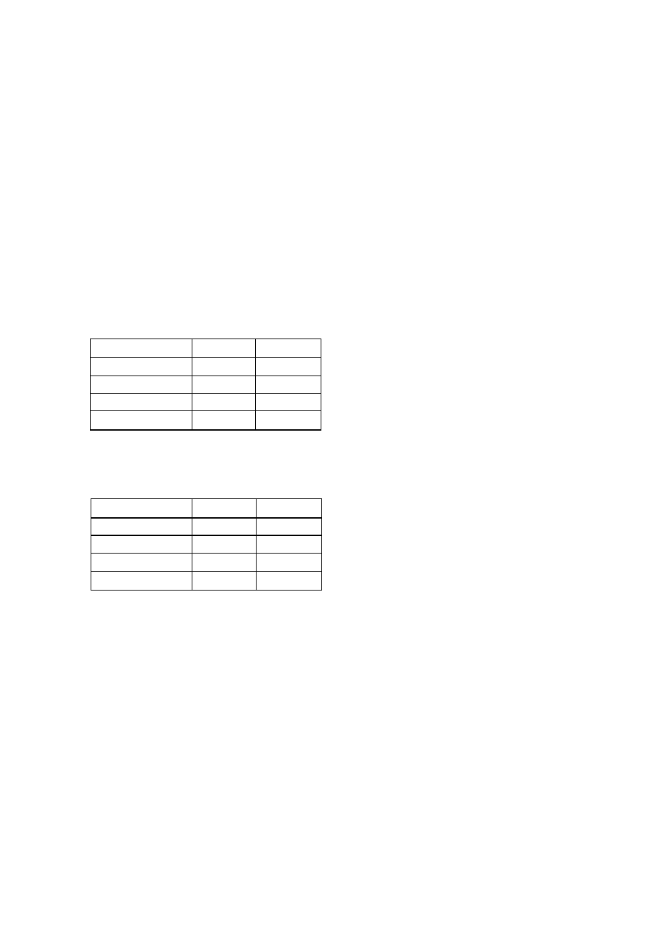
(2) SW2(bit1-2) Protocol
Protocoi
biti
bit2
TOSHIBA-P
Off
Off
TOSHIBA-D
On
Off
Reservel
Off
On
Reserve2
On
On
(3) SW2 (bit3-4) Bit Rate
Protocol
bit3
bit4
1200bps
Off
Off
2400bps
On
Off
4800bps
Off
On
9600bps
On
On
(Dome base switch:S301)
This is RS422 termination switch iocated near the BNC connector,
in daisy chain operation system, the farthest dome from the controlier is
turned ON.
For exampie, when the controlier is connected with three dome cameras
in the direct mode, the only furthest dome camera from a controller is
turned ON. The other dome camera is turned OFF. (It is OFF at the time
of shipment.)
ON and OFF are as in a figure.
- 3 2 -