Carrier HS070-160 User Manual
Page 24
On the sensor bus terminal strips, terminal of the
module is connected to terminal 1 of each of the
other modules; terminals 2 and 3 are connected in the
same manner. (See Fig. 13.) If a terminal 2 wire is con-
nected to terminal 1, the system will not work.
in the
units, the processor module,
voltage relay module, and keyboard! display module are
all powered from a common 21
power source which
connects to terminals 1 and 2 on the power input strip of
each module. A separate source of 12.5
power is used
to power the EXV driver module through terminals 1 and
2 on the power input strip.
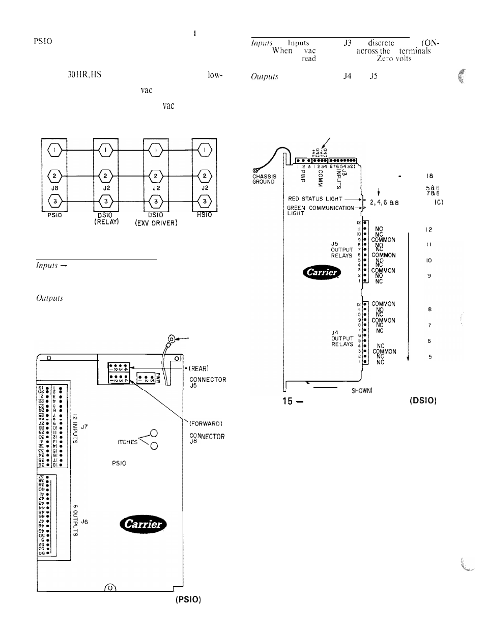
Low-Voltage Relay Module (DSIO) (Fig. 15.)
- -
on strip
arc
inputs
OFF).
24
are applied
2
in
a channel it is
as an ON signal,
is read
as an OFF signal.
Terminal strips
and
are internal relays
whose coils are powered-up and powered-off by a signal
from the microprocessor. The relays switch the circuit to
which they are connected. No power is supplied to these
connections by the DSIO module.
S E N S O R B U S C O N N E C T O R
INPUTS : 24 VAC
CHANNEL I J3 PINS
I
2 -
3 -
2
3 8 4
4 -
+
ARE GROUND
Fig. 13
Sensor Bus Wiring
COMMON
C H A N N E L
Processor Module (PSIO) (Fig. 14.)
Each input channel has 3 terminals; only 2 of
the 3 terminals are used. The application of the machine
determines which terminals are used. Always refer to the
individual unit wiring for terminal numbers.
Output is 24 vdc. Again, there are 3 terminals,
only 2 of which are used; which 2 depends on the appli-
cation. Refer to unit wiring diagram.
NOTE: Both address switches must be set at zero.
COMMON
NO
CHASS IS
G R O U N D
N E T W O R K
SENSOR BUS
ADDRESS ADJUSTMENT
I
(NOT
ON UNDERSIDE.
Fig,
Low-Voltage Relay Module
ADDRESS
SW
Fig. 14
Processor Module
24