Carrier HS070-160 User Manual
Page 13
NOTE: The control does not detect circuit breaker
failures. If a circuit
trips on the lead compressor
in a circuit, a
pressure failure
be indicated;
on the other compressors, no failure
be indicated.
Shut off the main
power to the unit. Turn on control power, then step
through the Quick Test to the proper compressor number
(i.e., failure code
is
Next, energize the
step. If the step works correctly, then the failure code
is due to:
.
l
l
back wire from
strip to
strip
l
Ground wire and
feeds reversed on one or more
points on
The
ground wire
terminals 2, 4, 6 and 8. Feeds
compressors Al,
A2,
and
connect to pins I, 3, 5 and 7.
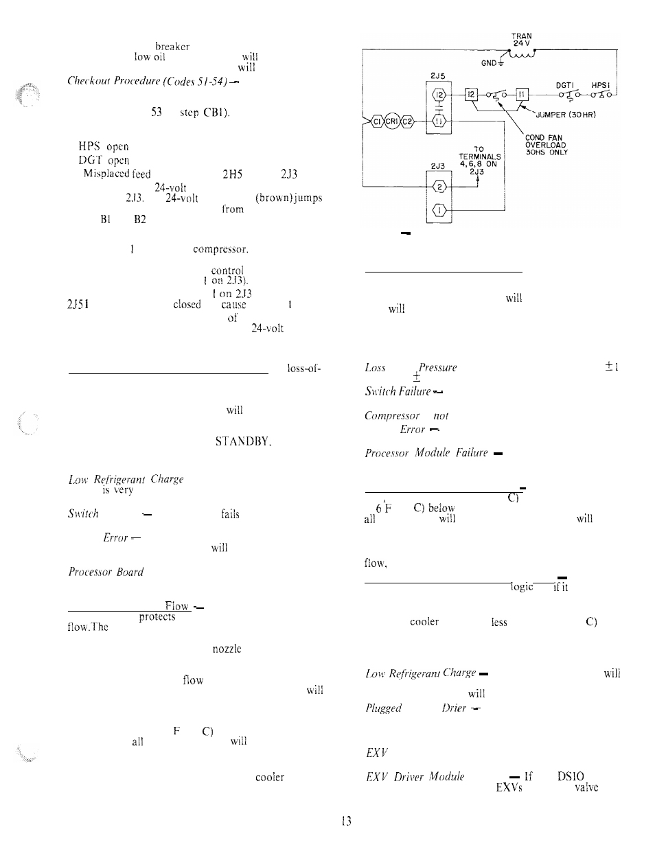
The processor closes the contacts between 255 ter-
minals 12 and I to start the
(See Fig. 3.) The
safeties shown to the right of 2.15 must be closed for
power to reach the compressor
relay (CR 1) and
the feedback input (terminal
Failure of power to terminal
when contacts
I and I2 should be
wilt
a code 5 alarm.
Terminal 2 on 293 is the other leg the compressor Al
feedback channel. It is connected to the
ground.
Code 59 and 60, Loss of Refrigerant Charge
A
charge switch is connected to the high-pressure side of
the refrigerant system. The microprocessor monitors this
switch directly; if it opens, all the compressors in the
circuit will be locked off, the alarm
be energized and
the display code will appear when the alarm display is
accessed. To reset, use the manual reset method (move
the RUN/STANDBY switch to
then back
to RUN).
Following are some possible causes for this alarm:
If the system refrigerant
charge
low, the microprocessor will detect this
through the switch and indicate the error.
Failure
If the switch
open, the micro-
processor will detect this and indicate an error.
Wiring
If there is a wiring error that causes an
open circuit, the microprocessor
treat this as an open
switch and indicate an error.
Failure
If the hardware in the pro-
cessor module fails in a manner that the switch cannot
be read properly, an error may be indicated.
Code 61, No Cooler
The microprocessor con-
tains logic that
the cooler against loss of cooler
cooler entering and leaving water temperature
sensors are used for this purpose. The leaving thermistor
is located in the leaving water
and the entering
sensor is located in the first cooler baffle space in close
proximity to the cooler tubes as shown in Fig. 4. When
there is no cooler water
and the compressors are
operating, the leaving water temperature thermistor
indicate no temperature change. But the temperature of
the entering water will drop rapidly and the entering
water thermistor will detect this. When the entering water
temperature drops to 5 (2.8
below the leaving water
temperature,
the compressors
stop and code
no. 61 will be displayed. To correct, use manual reset
method (after cooler water Row is resumed).
The error will be caused either by no
flow or
if the water is flowing in the wrong direction through the
cooler or if the thermistors have been interchanged.
Fig. 3
Compressor Al Control Wiring (Typical)
Code 63 and 64, Low Oil Pressure
A low oil pressure
switch is installed on the lead compressor in each circuit.
If the switch opens during operation of the compressor,
all the compressors
in
the circuit
be shut off, the alarm
light
be energized and the appropriate display code
shown. The switch will be bypassed for one minute during
start-up and for 45 seconds during normal operation. The
manual reset method must be used to reset this safety.
Possible causes for failure are:
of’
Oil
If the oil pressure is below 5
psig (34.5 6.9 kpa), the switch will open.
If the switch fails open, a failure will be
indicated.
is
running.
wiring
If a wiring error exists that causes an
open circuit, an error will occur.
If the hardware on the
processor module fails in a manner that the switch cannot
be read properly, an error may be indicated.
Code 65, Cooler Freeze Protection If the leaving water
temperature is below 35 F (1.7
for a water chiller or
is
(3.3
the set point for brine applications,
compressors
be stopped. This safety
auto-
matically reset when the water temperature is 6 F (3.3 C)
above the set point.
The causes for this failure are usually due to low cooler
or extremely rapid load changes.
Code 66 and 67, High Suction Superheat
The micro-
processor contains the following
and
is satisfied,
all the compressors in the circuit will be stopped:
Suction superheat is greater than 75 F (4f.7 C), and
saturated
suction is
than 55 F (12.8
and
these 2 conditions have been true for more than5 minutes.
To reset this, use the manual reset method.
Causes
for this failure are:
A low refrigerant charge
not allow the correct amount of refrigerant to be fed to
the evaporator, which
result in a high superheat.
F i l t e r
If the liquid line filter drier
becomes plugged, it can result in not enough refrigerant
being fed to the evaporator, which results in a high super-
heat failure.
Failure
If the EXV fails to open enough to feed
the proper amount of refrigerant, the error will occur.
Failure
the
module
hardware that controls the
fails, the
will
not move.