Carrier HS070-160 User Manual
Page 20
- M U F F L E R S
MUFFLERS
COMPRESSORS
COMPRESSORS
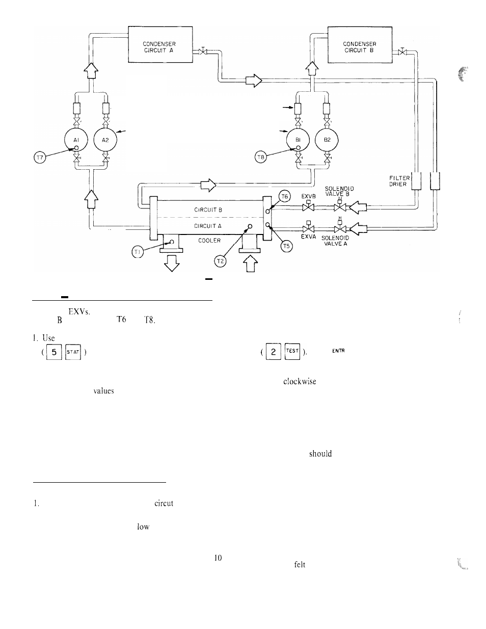
Fig. 9
Thermistor Locations
Step
4
Check Thermistors That Control EXV
Check thermistors that control processor output voltage
pulses to
Circuit A thermistors are T5 and T7.
Circuit thermistors are
and
Refer to Fig. 9 for
location.
the temperature subfunction of the status function
to determine if thermistors are reading
correctly.
2. Check thermistor calibration at known temperature
by measuring actual resistance and comparing value
measured with
listed in Table 8.
3. Make sure that thermistor leads are connected to
proper pin terminals at 157 terminal strip on processor
module and that thermistor probes are located in
proper position in refrigerant circuit (Fig. 9).
When above checks have been completed, actual
operation of EXV can be checked by using procedures
outlined in Step 5.
Step 5
Check Operation of the EXV
Use following
procedure to check actual operation ofelectronic expan-
sion valves.
Close liquid line service valve for
to be checked
and run through the Quick Test step (in subfunction
3 of test function) for the lead compressor in that
circuit to pump down the
side of the system.
Repeat test step 3 times to ensure that all refrigerant
has been pumped from low side.
NOTE: Be sure to allow compressors to run full
seconds at each step.
2. Turn OFF compressor circuit breaker(s). Close com-
pressor service valves and vent any remaining refrig-
erant from low side of system.
3. Remove screws holding top cover of EXV. Carefully
remove top cover, using caution to avoid damage to
the motor leads. If EXV plug was disconnected during
this process, reconnect it after the cover is removed.
4. Enter appropriate EXV Quick Test step for EVXA or
EXVB in the outputs subfunction of the test function
q
Press
to initiate test. With cover
lifted off the EXV valve body, observe operation of
valve motor and lead screw. The motor should turn
in the
direction and the lead screw should
move down into the motor hub until the valve is fully
closed or fully open depending on whether you initiate
the open or close test step for that valve. Lead screw
movement should be smooth and uniform from fully
open to fully closed position, or from fully closed to
fully open.
If valve is properly connected to processor and receiv-
ing correct signals, yet does not operate as described
above, the valve
be replaced.
The operation of the EXV valve can also be checked
without removing the top cover. This method depends on
the operator’s skill in determining whether or not the
valve is moving, To use this method, initiate the Quick
Test to open the valve. Immediately grasp the EXV valve
body with the hand. As the valve drives open, a soft,
smooth pulse will be felt for approximately 26 seconds
as the valve travels from fully closed to fully open. When
the valve reaches the end of its opening stroke, a hard
pulse will be felt momentarily. Drive the valve closed and
a soft, smooth pulse will be felt for the 26 seconds necessary
for the valve to travel from fully open to fully closed.
When the valve reaches the end of its stroke, a hard pulse
will again be
as the valve overdrives by 50 steps. The
valve should be driven through at least 2 complete cycles
to be sure it is operating properly. If a hard pulse is felt
for the 26 second duration, the valve is not moving and
should be replaced.
20