Carrier HS070-160 User Manual
Page 19
Electronic Expansion
CHECKOUT
t o
diagnose and correct
problems, For an
of EXV operation, see
2
Step 1
Check EXV Driver Outputs
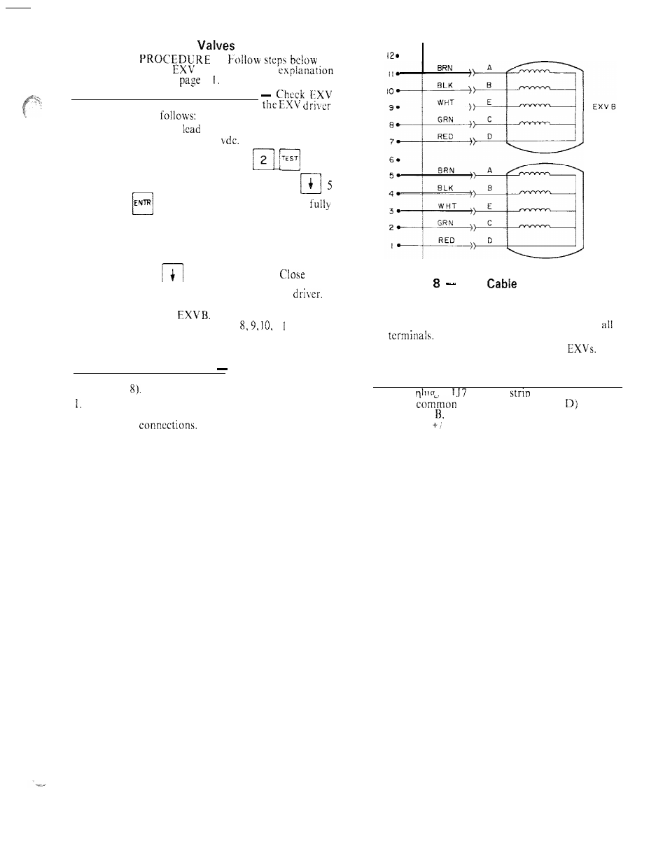
output signals at appropriate terminals on
module (Fig. 8) as
Connect positive test
to terminal 1 on EXV driver.
Set meter for approximately 20
Enter outputs sub-
function of test function by pressing
, then
advance to EXVA Open Quick Test by pressing
times. Press
. The driver should drive the EXV
open. During the next several seconds connect the nega-
tive test lead to pins 2.
3,
4 and 5 in succession. Voltage
should rise and fall at each pin. If it remains constant at a
voltage or at zero volts, remove the connector to the valve
and recheck. Press
to reach the EXV A
Quick
Test. If a problem still exists, replace the EXV
If
the voltage reading is correct, the expansion valve should
be checked. Next, text
Connect the positive test
lead to pin 7 and the negative to pin
1 in succes-
sion during the EXVB Quick Test.
Step
2
Check EXV Wiring
Check wiring to elec-
tronic expansion valves from terminal strip on EXV
driver (Fig.
2. Check for continuity and tight connection at
pin
3. Check plug connections at driver and at
He sure
EXV connections are not crossed.
Step 3
Check Resistance of EXV Motor Windings
Remove
at
terminal
and check resistance
Check color coding and wire connections. Make sure
they are connected to correct terminals at driver and
between
lead (red wire, terminal
and remain-
EXV plug
ing leads A,
C. and E (see Fig. 8). Resistance should
be
25 ohms
-2
ohms.
EXV A
Fig.
EXV
Connections to
EXV Driver Module
1 9