Carrier HS070-160 User Manual
Page 23
Modules
Turn controller power off before servicing
controls. This is to ensure safety and prevent damage
to the controller.
PROCESSOR MODULE
LOW-VOLTAGE
R E L A Y M O D U L E
E X V D R I V E R
MODULE
The
and
modules
perform continuous diagnostic evaluations of the condi-
tion of the hardware. Proper operation of these modules
is indicated by
(light emitting diodes) on the front
surface of the
and on the top horizontal surface
of the PSIO.
Red LED:
at a 3 to 5 second rate indicates
proper operation
Lit
indicates a problem requiring replace-
ment of the module
indicates the power
be checked.
If there is no input power, check fuses. If fuse is bad, check
for shorted secondary of transformer, or for bad module.
Green LED: (On a
this the green LED closest to
the
connectors. The other green LED on the
module indicates external communications, when used.)
The green LED should always be blinking
on; it indicates that the modules are communicating
properly.
a green LED is not blinking, check
the red LED is normal, check the module address
switches. See Fig. 9. The proper addresses are:
(Processor Module)
(Relay Module)
32
Driver Module) -- 50
indicate a communication failure, check
the
the
module for proper seating.
connection is
and the condition per-
sists,
the
module.
only a
module indicates a communication
check the
plug on that module for proper
seating. a good connection is assured and the condition
persists.
the
All
operating
rests in the
(processor
the
that controls
the unit. This
monitors conditions through input
and output ports and
voltage
module and
module).
The machine
communicates with the micro-
processor through
module
module). Communication between
and the
other modules is accomplished by a
bus.
These 3 wires run in
from
to module.
Each module in a panel is numbered
2,
Each
terminal strip on a module is
terminal strip number on the machine schematic com-
bines the module and strip numbers. For example,
is
terminal strip
on module 2. The module numbers can
be found on the component arrangement label.
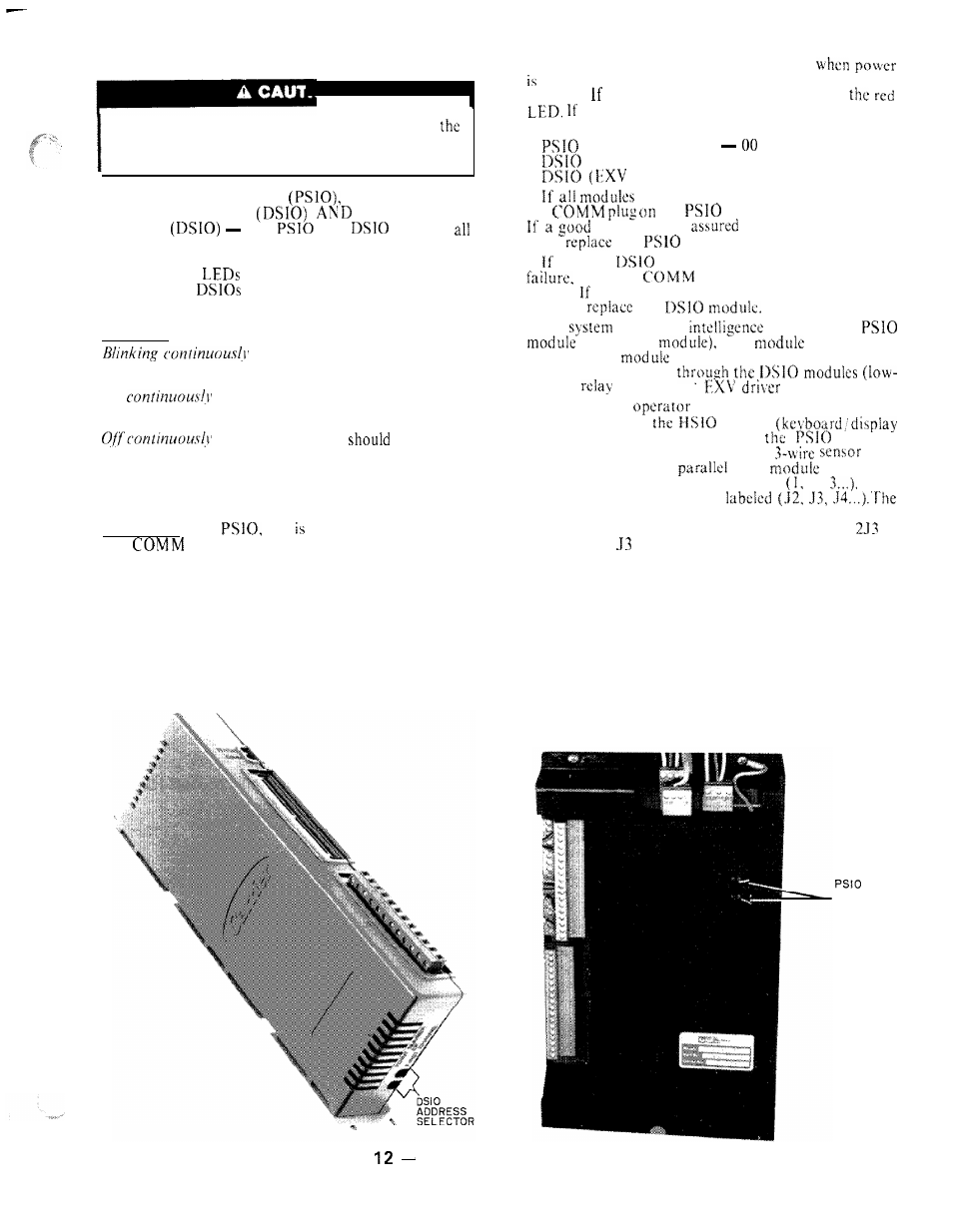
ADDRESS
SELECTOR
Fig.
Module Address Selector Switch
Locations
2 3