Replace the gigabit interface converter, Gbic, Gbic slot – Cisco 7200 VXR User Manual
Page 39: Alignment groove, Plug
39
To replace the CompactFlash Disk in the NPE-G1, see the “Prepare for Installation” section on page 6.
Also see
at
http://www.cisco.com/en/US/docs/routers/7200/install_and_upgrade/flash_disk_install_config/6452fd.html, and
at
http://www.cisco.com/en/US/docs/routers/7200/install_and_upgrade/npe-nse_memory_install/memory.html.
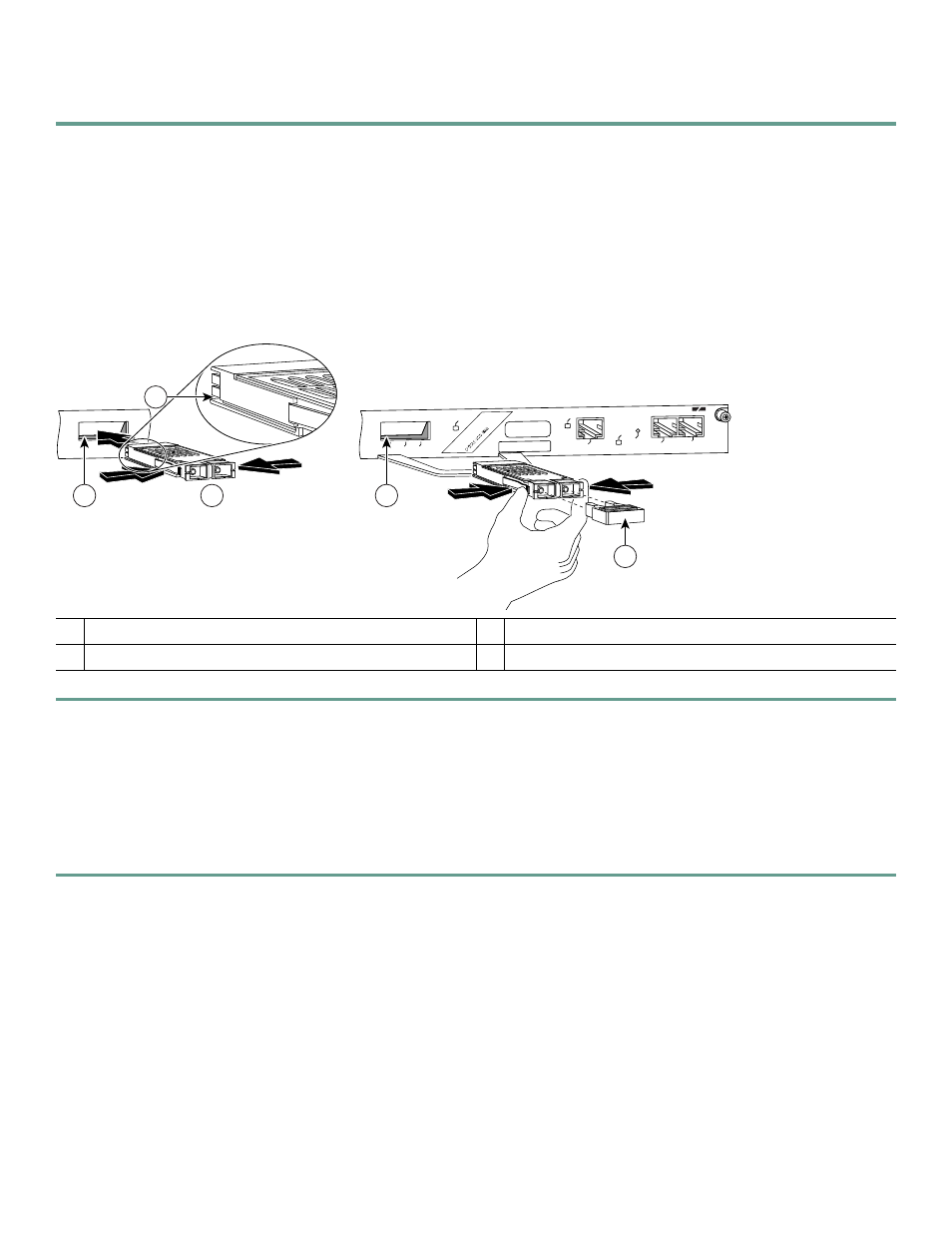
Replace the Gigabit Interface Converter
Figure 21
Replacing the GBIC
Step 1
Remove the Gigabit Ethernet Gigabit Interface Converter (GBIC) cables from the GBIC slot on the I/O controller or on
the NPE-G1.
Step 2
Remove the GBIC from the I/O controller or the NPE-G1.
Step 3
Locate the alignment groove (2)on the GBIC. (The label faces up.)
The GBIC is keyed so that it cannot be inserted incorrectly.
Step 4
Insert the GBIC into the slot on the I/O controller or the NPE-G1.
Step 5
Attach the GBIC cables. Also see the “SFP and GBIC Interface Cables Installation” section on page 20.
1
GBIC
3
GBIC slot
2
Alignment groove
4
Plug
LINK
C
LA
S
S
1
LE
D
P
R
O
D
U
C
T
P
R
O
D
U
K
T
M
IT K
LA
S
S
E 1
LE
D
P
R
O
D
U
IT
A
V
E
C
V
O
YA
N
T
D
E
L
D
E
C
LA
S
S
E
1
P
R
O
D
U
C
T
O
LE
D
D
E
C
LA
S
E
1
ETHERNET GIGABIT ETHERNET INPUT/OUTPUT CONTROLLER
CONSOLE
AUX
E 0
LINK
GE 0
RX
TX
CPU
RESET
IO PW
R
OK
1
2
57017
4
3
3